Set Buddy
So, I’m a regular gymgoer, but there’s one thing killing my lifts.
My phone.
I find myself getting sucked in to Spotify, Instagram, Ebay, Facebook Marketplace, etc. when I should be pumping iron!
The ideal rest time between sets for hypertrophy is 2-3 minutes, but I often find myself taking long breaks that can last up to eight minutes. I decided that, if I wanted to increase my bench PR from 335 to 365 by the end of my senior year, this needed to stop. So, I decided to create a portable device that could correct my bad habits.
Is this in any way practical?
No, not really. A dedicated, battery powered, ESP32 is a lot less practical than a simple phone app, which would be much cheaper and easier to make. However, I chose to build an entire device around the idea for two reasons:
1.) A device dedicated to timing sets allows you to leave your phone in a locker or car, letting you focus entirely on the workout and not Instagram Reels.
2.) 3D printed, battery powered, compact devices are neat.
Still, I wouldn’t say it’s entirely impractical, as the device only took a couple weeks of work to develop and less than fifteen bucks to make with parts from AliExpress.
The Parts
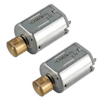
Initially, I bought a motor off of AliExpress, but it turned out to be a little too violent. So, I downsized to one I found on Amazon.
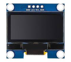
For the display, I chose a standard SSD1306 OLED. The SSD1306’s low cost, great documentation, and surprisingly good brightness made it an easy choice.
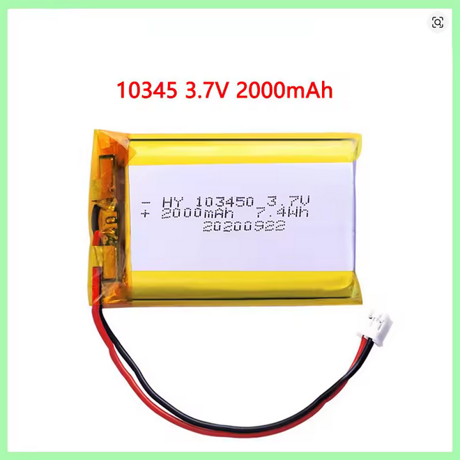
I wanted a big-ass battery so I wouldn’t have to charge the device that often. I picked out a 2000mAh 103450 cell that should be able to keep it going for over ten hours of continued use; so about 7 good workouts. Honestly, I could’ve made this thing MUCH slimmer by using a smaller battery, but I instead chose to prioritize battery life.
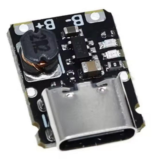
I went with a standard USB-C TP4056 module for pretty standard 4.2V charging at 1A.
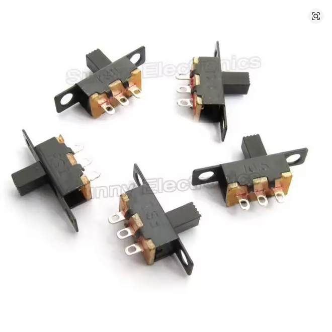
I got these small 19 x 6 x 13mm slide switches on AliExpress designed for 2.5mm openings.
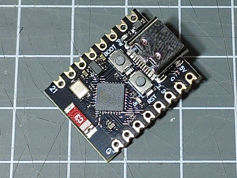
The heart of the device, the microcontroller, needed to be somewhat power efficient and very compact. It also needed to have enough GPIO for 5 buttons and a MOSFET, as well as I2C support for SSD1306 display. Originally, I was going to go with a Pi Pico for its great power efficiency, but I later settled on an ESP32-C3 based dev board called the “Super Mini” because it was cheaper, faster, smaller, and had better SSD1306 libraries that were more familiar to me. They’re cheap on AliExpress and well known throughout the ESP32 community.
The Plan
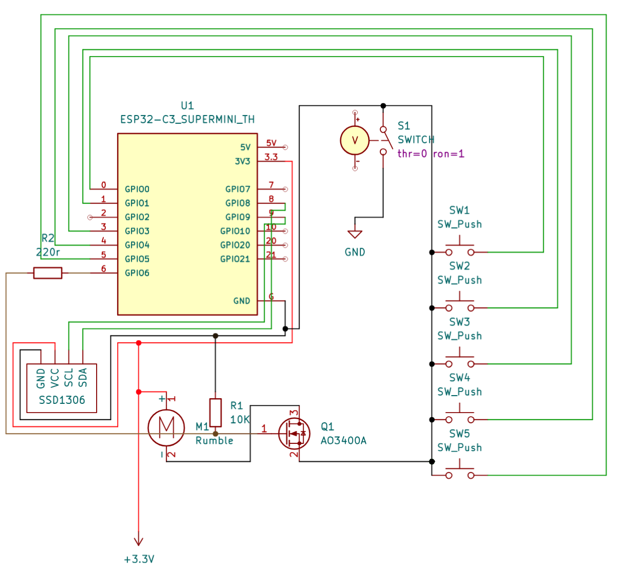
The 3.3V and GND power symbols represent the output of the TP4056, which is not pictured in the schematic. One end of each button is wired straight to one of the ESP’s GPIO pins and pulled down internally, while the other is wired to ground. Similarly, the OLED’s SCL and SDA pins are wired to pins 8 and 9 on the ESP, which are the Super Mini’s default I2C pins. The only other component of note is the A03400A N-channel MOSFET. It’s set up so that the drain is wired to the motor, the source is wired to GND, and the gate is connected to pin 6 of the ESP32 via a 220r resistor. Additionally, the gate is also pulled down to ground via a 10K resistor.
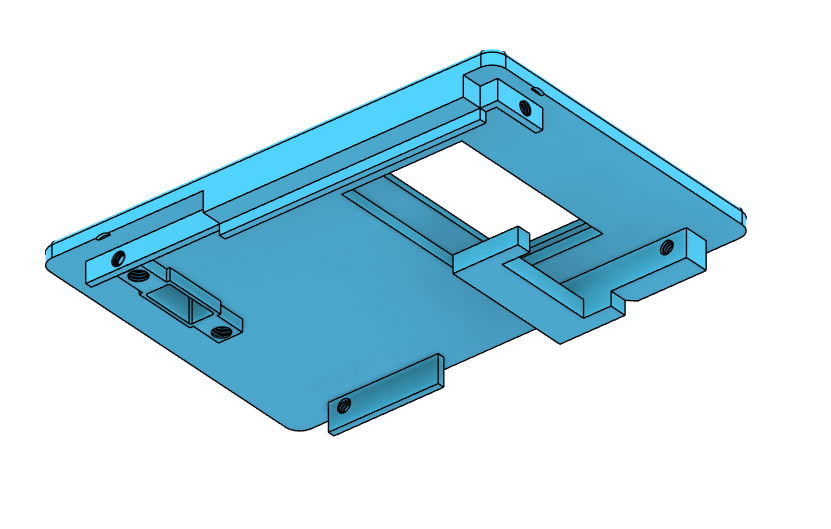
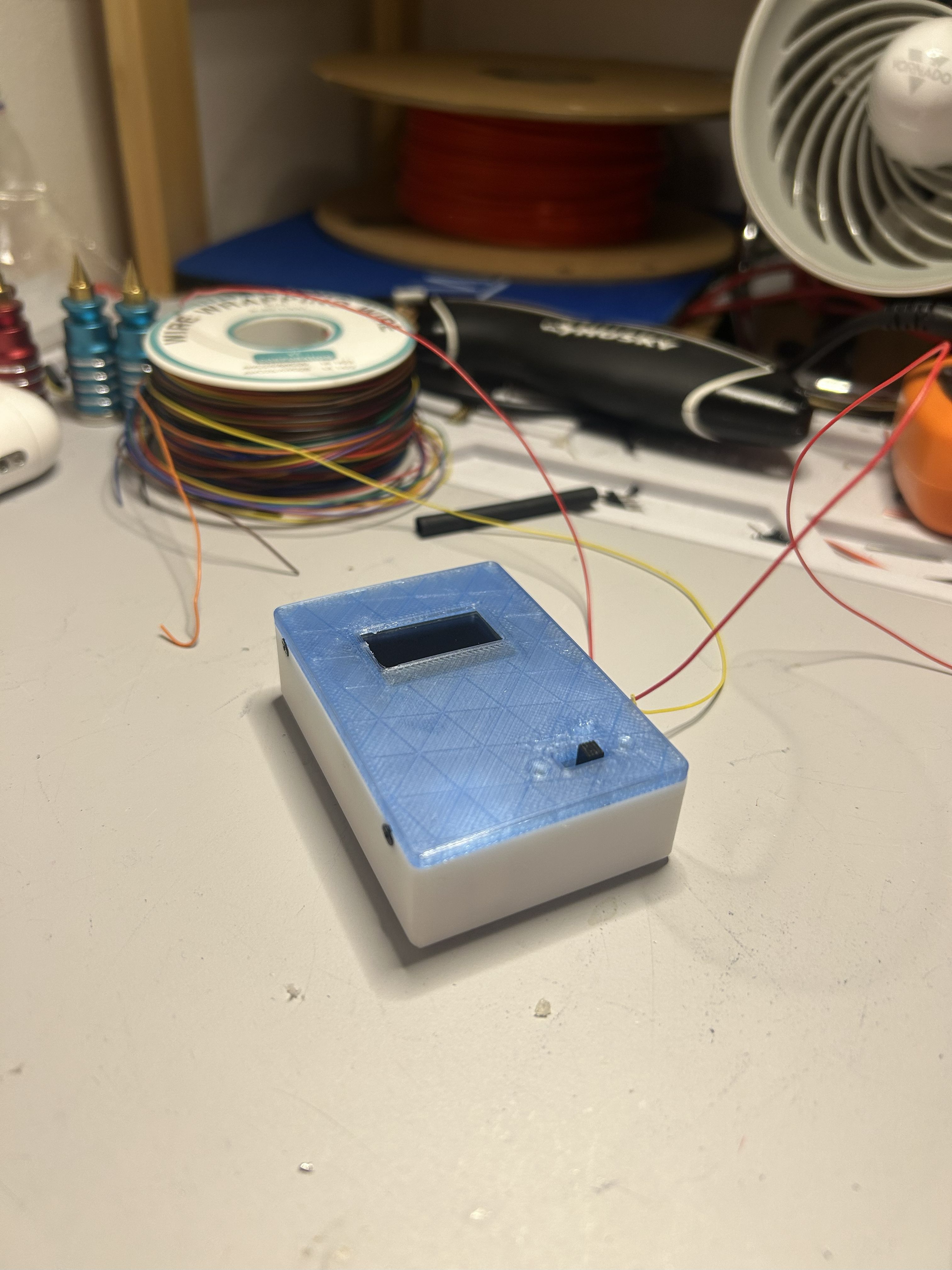
The CAD
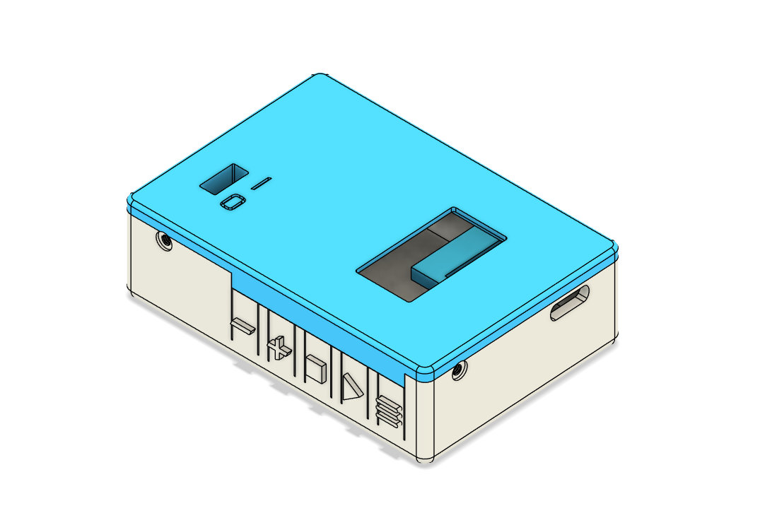
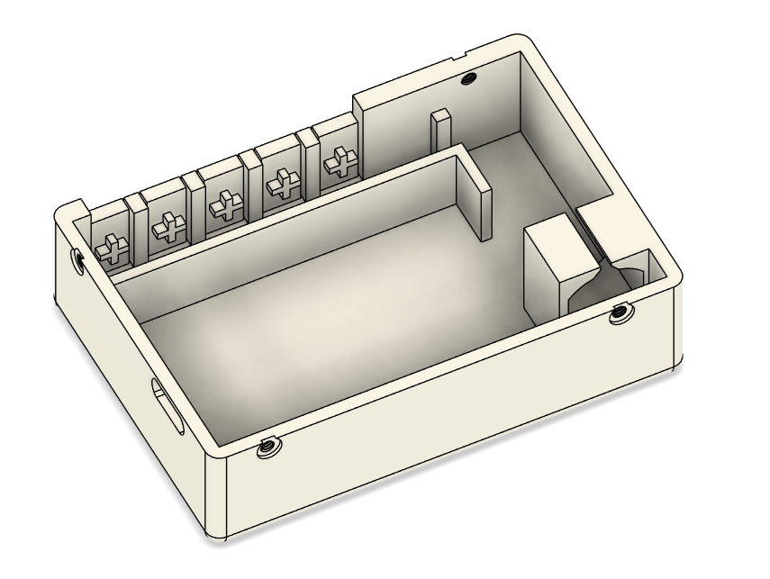
This was where the majority of my time spent on this project went. The shell is designed so that the battery is fitted into the base of the device. Then, the TP4056’s USB-C port is fitted into its hole. The motor is held firmly in place by a bracket seen on the left side of the third picture; because the motor vibrates violently during the device’s regular operation, I used a bit of glue as well. Near the bottom of the third picture, you can see the pushbuttons (6x6x6mm), glued in place. I went for a button design that integrates them into the bottom shell in an attempt to keep printing and assembly simple. The downside to this is that the buttons feel a little mushier than I would’ve liked, but in all I think it was a necessary trade off.
The top shell features a rectangular hole for my power switch (held in place with M2.5 screws). There are four threaded holes present in both the upper and lower shells that allow for M2 screws to hold the Set Buddy together. The most noticeable feature of the upper shell is the “hook,” which is a simple screwless solution that keeps the TP4056 in place.
Click here to download it.
The Code
The code was really simple, I don’t have much to say about it. I used the Wire library and Adafruit’s SSD1306 libraries for the display and wrote some functions that update the display, handle input, and toggle the motor for certain intervals.
Click here to download it.
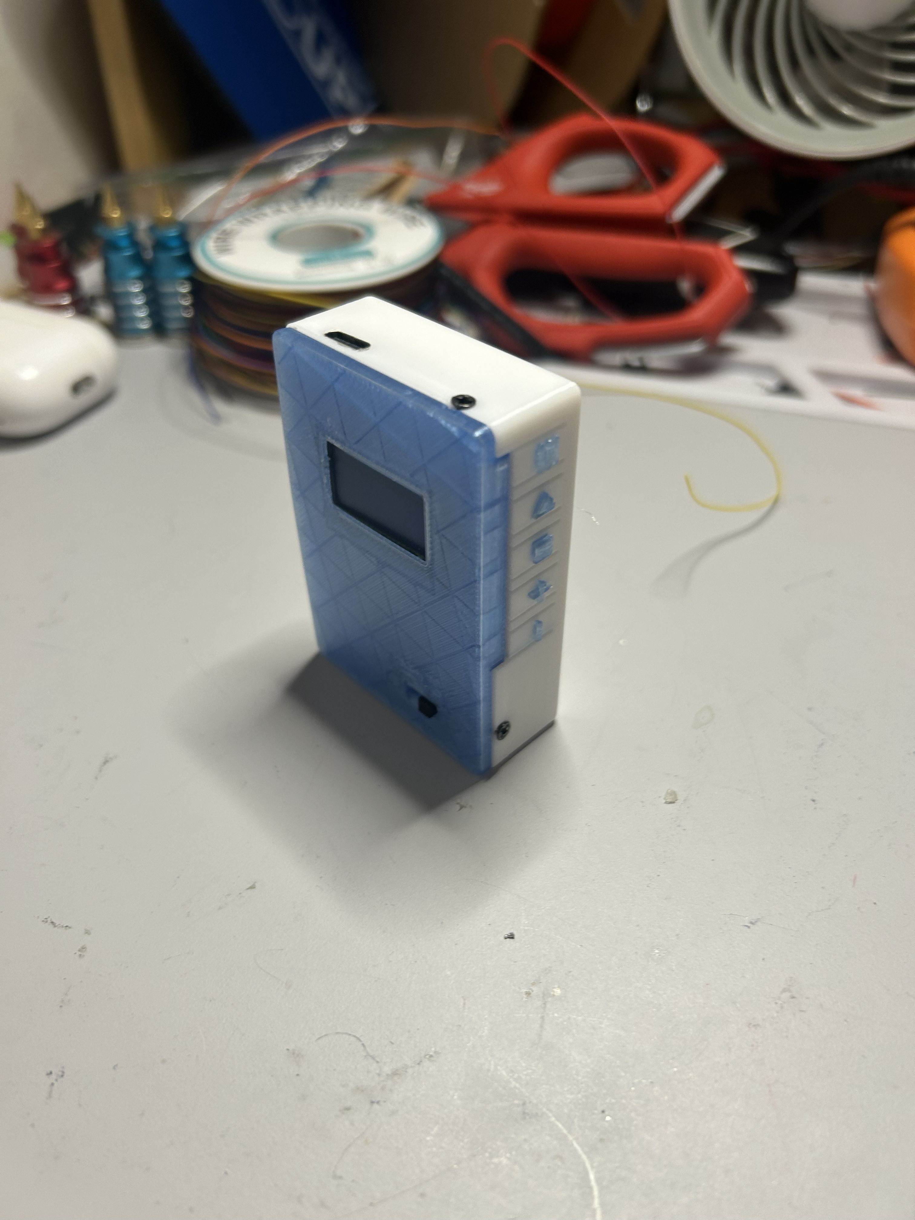
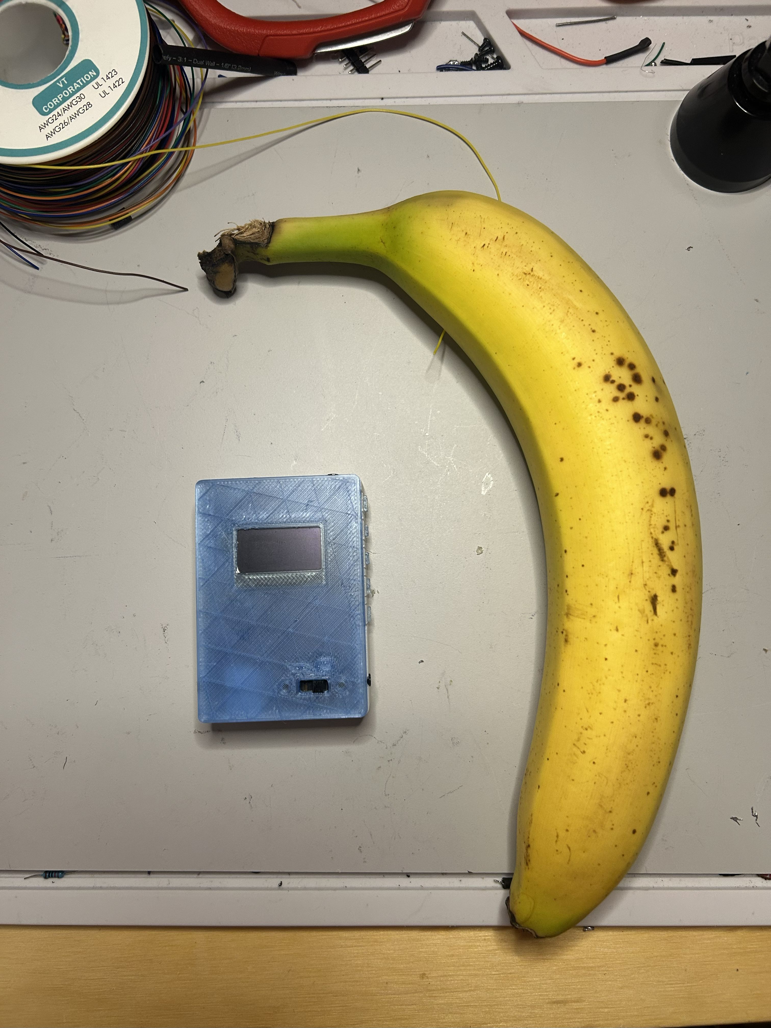
The Final Product
So, how does it actually work? Well, here’s what the buttons do:
Down (-) - Lowers timer by 15 seconds (minimum is 15s)
Up (+) - Increases timer by 15 seconds (maximum is 1000s)
Stop - While the timer is running, pressing the stop button will pause it. Pressing it again will stop and reset the device back to the original time.
Play - Starts the timer
Menu (3 lines) - Toggles between the four different vibration modes; some are… more urgent than others.
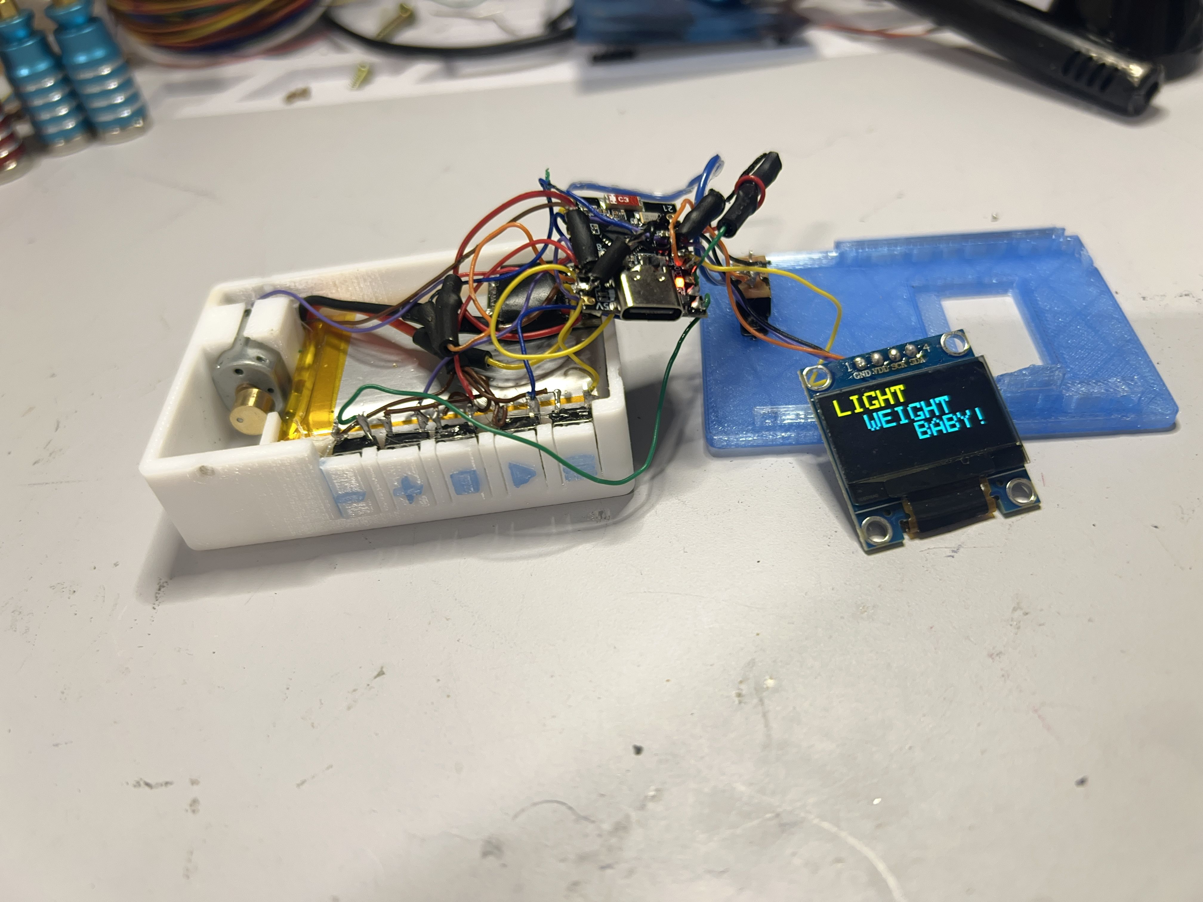
When the timer reaches 0, the device will vibrate and the user will be greeted with Ronnie Coleman’s famous: “LIGHT WEIGHT BABY!”
Pressing the stop button will stop the rumbling and return the user back to the device’s original state so that the timer can be started again once they have finished their set.
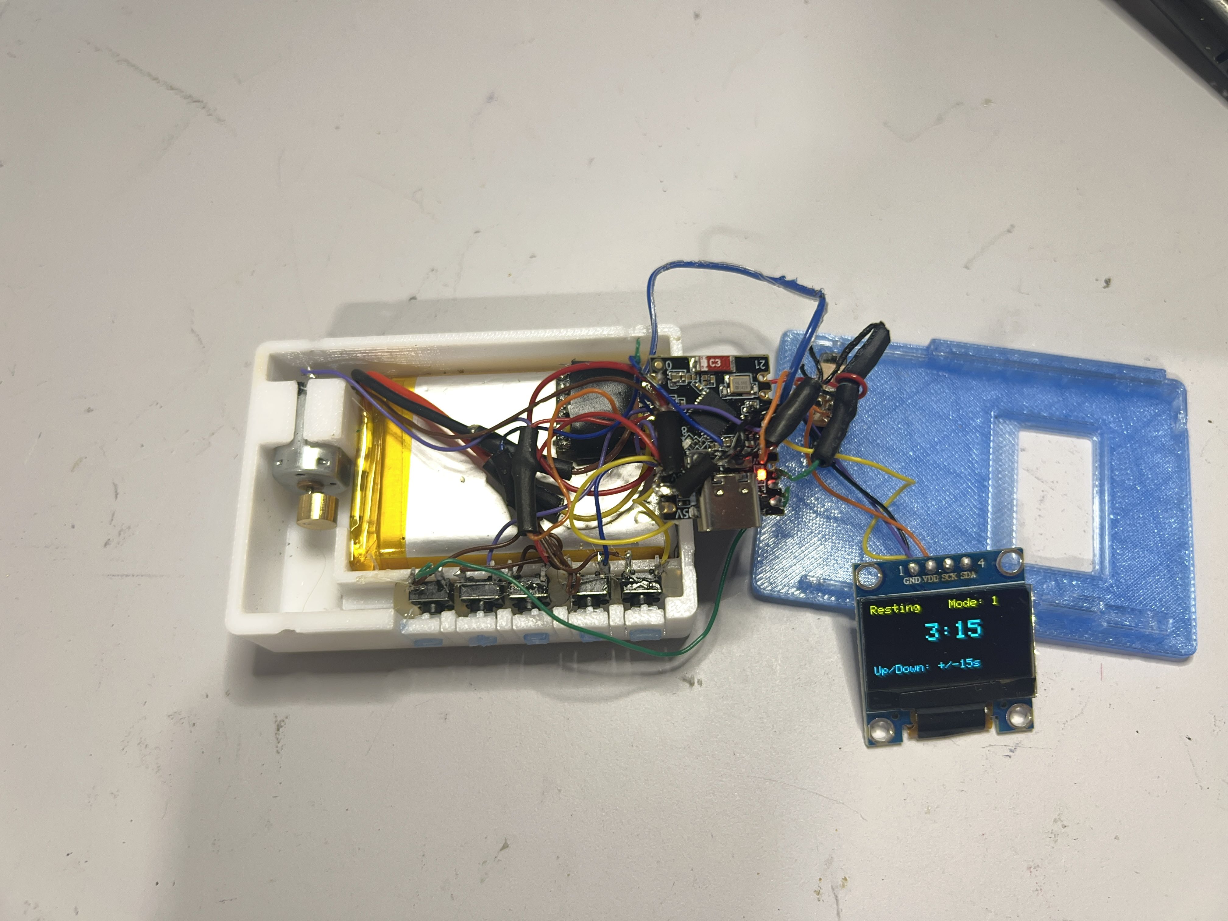
Hindsight
With it all assembled, I can say that it does the job well and looks very clean. In closing, there’s really only one thing I would have done differently: a PCB. I didn’t make one because I don’t have a lot of experience designing PCBs for compact devices like this, so I was worried that a PCB would add to the overall size of a device I wanted to keep small and convenient. Instead, I opted to simply manage a bunch of wires, stuffing them into the enclosure, a naive choice that I can now say was the wrong one. Every time I would assemble this thing, some solder joint would get pushed on by a bunch of wires and would inevitably break, leaving me to spend 10 minutes figuring out what had happened. A PCB would have avoided this issue completely, saving me some headache. My next planned project involves some more complex KiCad work, so hopefully by the time that’s done I’ll have some more experience (and free time) to rework this thing into a more elegant product.