JVC AV-20321 RGB MUX Mod
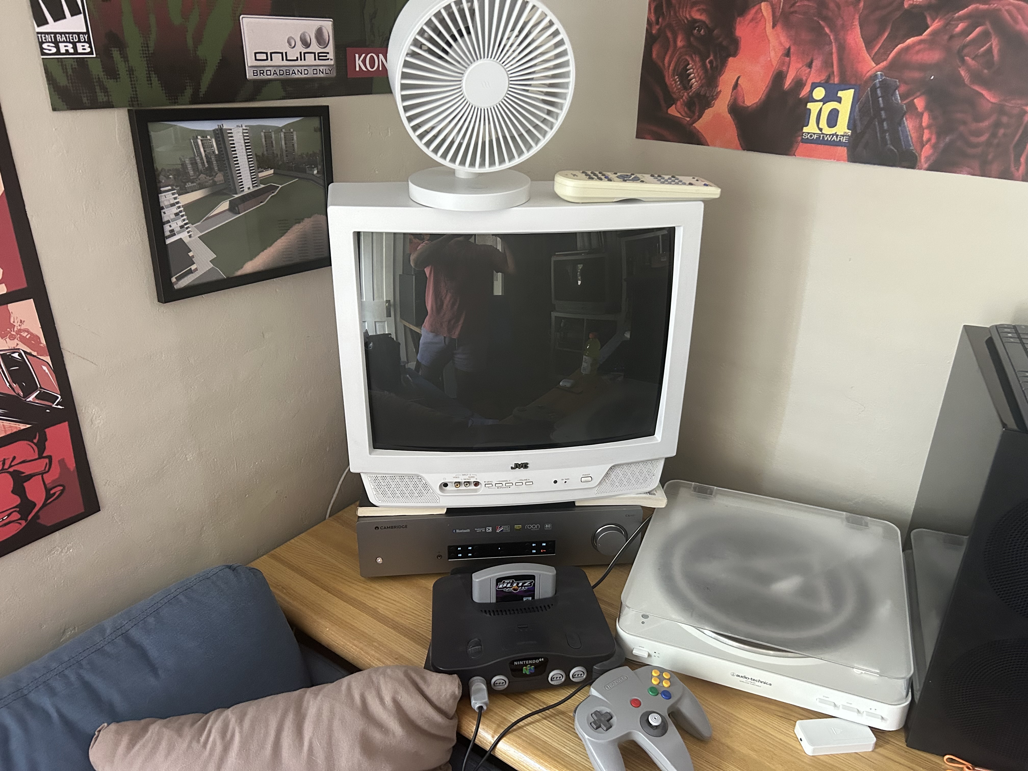
Recently, I got back into retro gaming and decided to seek out another, smaller CRT to complement my 27” JVC AV series. I wound up bringing home another JVC AV, this one a 20 inch that I scored on Marketplace for 30 bucks. It’s in almost perfect condition; it doesn’t appear to have been used regularly at all. Since it only supported composite input, I decided it would be the perfect candidate for my third RGB mod. In doing so, I hoped to realize the full potential of the JVC D-Series Tube with a sharper image (the AV series is basically just the renowned D-series with cheaper speakers and the same pristine picture quality).
RGB Mod Basics
The specific RGB Mod I will be attempting is an RGB Mux mod, which is unique in that it allows you to utilize the OSD (on screen display) while displaying an RGB picture. The premier resource for RGB Mux mods is sector.sunthar.com, a website containing guides for almost every common CRT chassis. If you’re unfamiliar with how an RGB mod works, Sunthar has a great write-up on the topic here. This page on the CRT Database is also helpful, and includes a list of CRTs that support Mux mods.
It’s important to note that the effects of an RGB mod vary wildly from TV to TV, as some CRTs have better comb filters than others. A comb filter is a circuit that filters out interference in composite signals, so TVs with great comb filters may not benefit from RGB mods as much as those with poor comb filters. Overall though, because RGB mods are cheap and only require basic soldering skills, I don’t see any reason to not mod your CRT if it’s moddable.
Another important note is that a sharper image is not necessarily better. There are a few consoles like the NES or Atari 2600 that I think look better with a blurrier composite signal. It’s nice, therefore, that RGB mods don’t interfere with the ability to use the stock composite inputs.
Required Materials
Sunthar RGB MUX Board
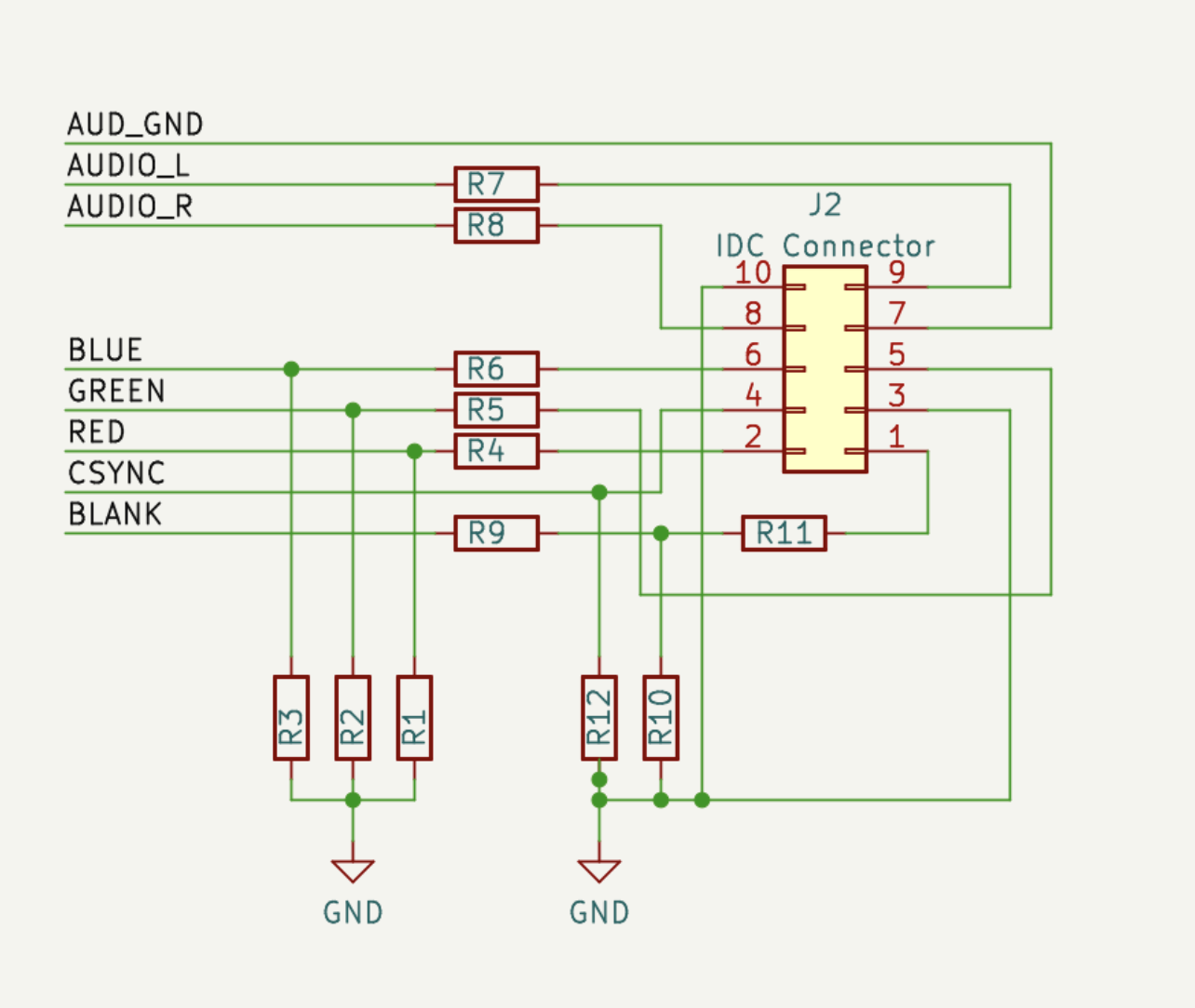
This board isn’t essential (I’ve done a mux mod solely on perfboard before), but it’s really cheap and saves so much headache that there’s no reason not to use it. It’s as simple as PCBs come, so you can get five of them for $5 from JLCPCB. It was designed by Sunthar; I used v1.3B for this project (link).
10 Pin Rainbow IDC Cable
This is what you’ll solder to the mainboard and connect to the MUX board.
If you ever buy from AliExpress like I did, make sure you crimp the cable correctly!!! Mine came reversed. Failing to fix it will send 5V to something that should not get 5V!!!!!
SCART Port (Female)
You can get these from AliExpress or Amazon. I would recommend finding the one with two threadable holes on either side of the port; I used one with no holes, as I had it on hand and it was convenient. Unfortunately, that meant that I would have to rely entirely on glue to secure the port to the shell. Thanks to the removable IDC Cable, this didn’t interfere with repairs or upgrades.
Assorted Resistors and a Diode
For my AV-20321, I used the values found in this table that were calculated for the AV-20020. I also later swapped the 220r terminating resistors for standard 75r, but there was little difference and I swapped back because the 220rs were a bit more vivid. The diode stops the 5V blanking signal from flowing back in to whatever input device (console) you have hooked up.
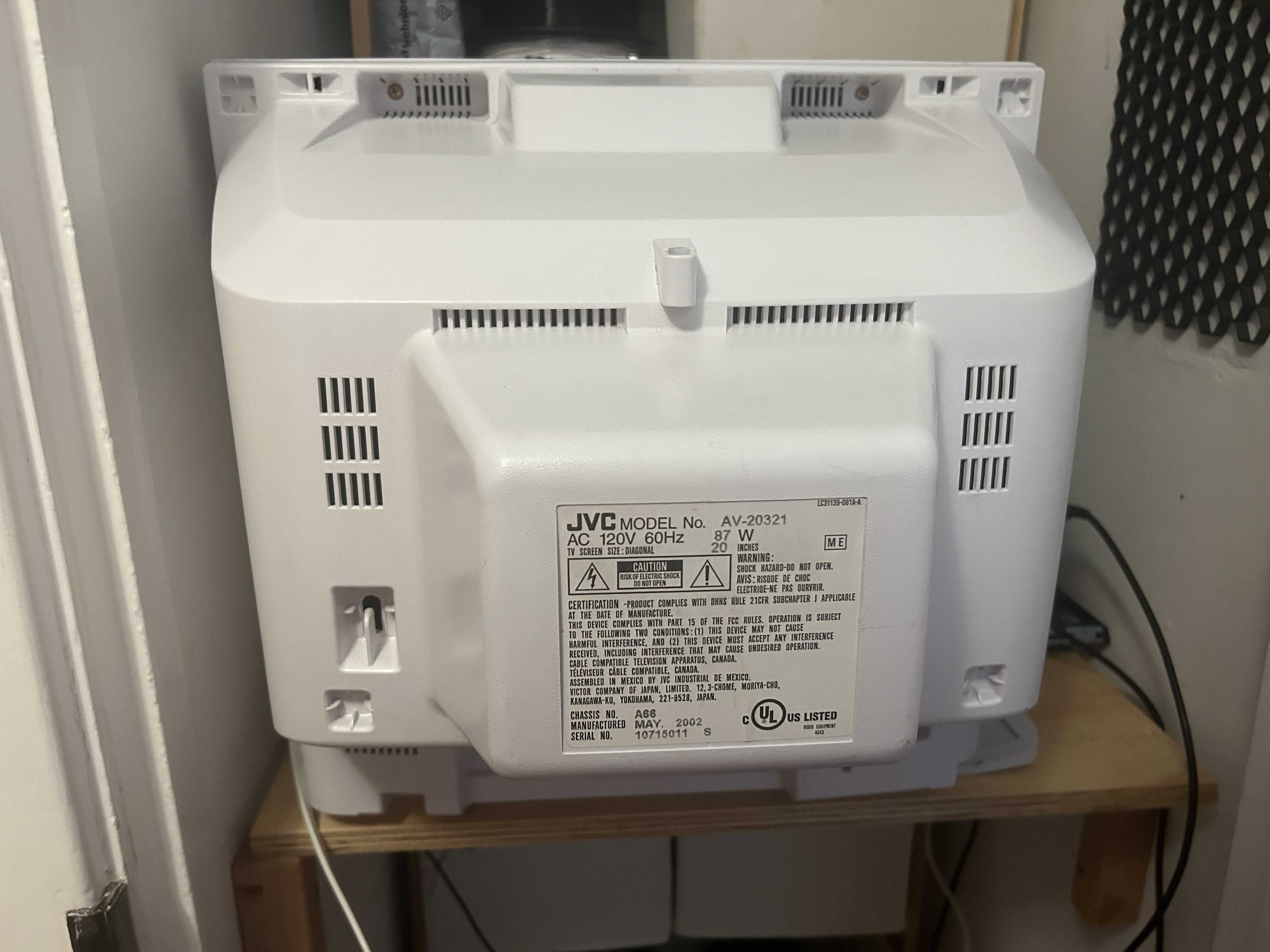
About the AV-20321
The AV-20321 isn’t a common model; the only thing I could scrounge up online was a single Reddit post and a copy of the manual. Thankfully, this doesn’t particularly matter, as the 20321 is a later revision of the JVC AV-20020 that has been somewhat documented. The TV is also practically the same as its black counterpart, the AV-20320, as the last digit of the TV’s model number, “1,” indicates that this is the white variation of the CRT. White CRTs are much less common than black or silver CRTs, making this one an even cooler find.
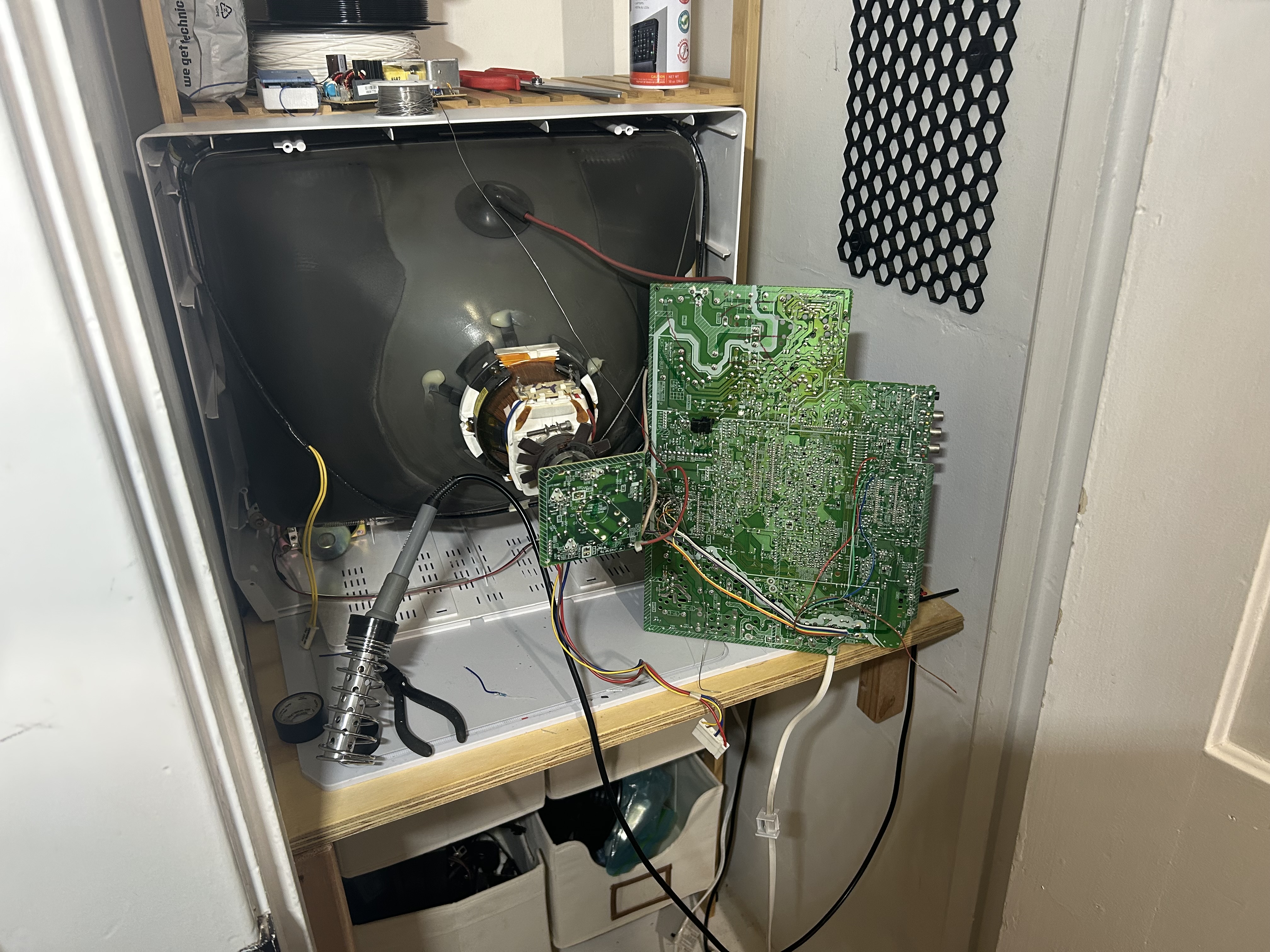
The Mod
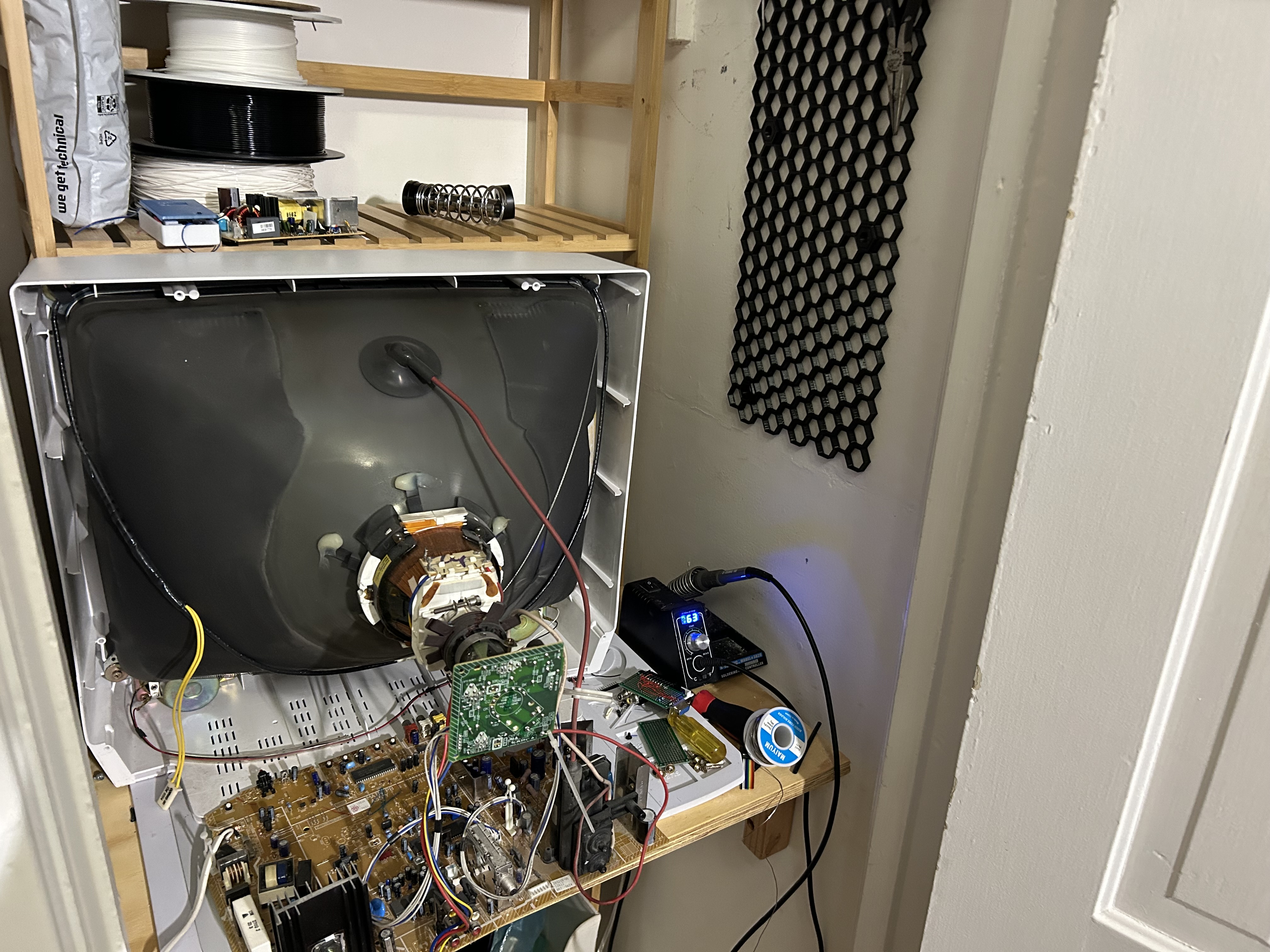
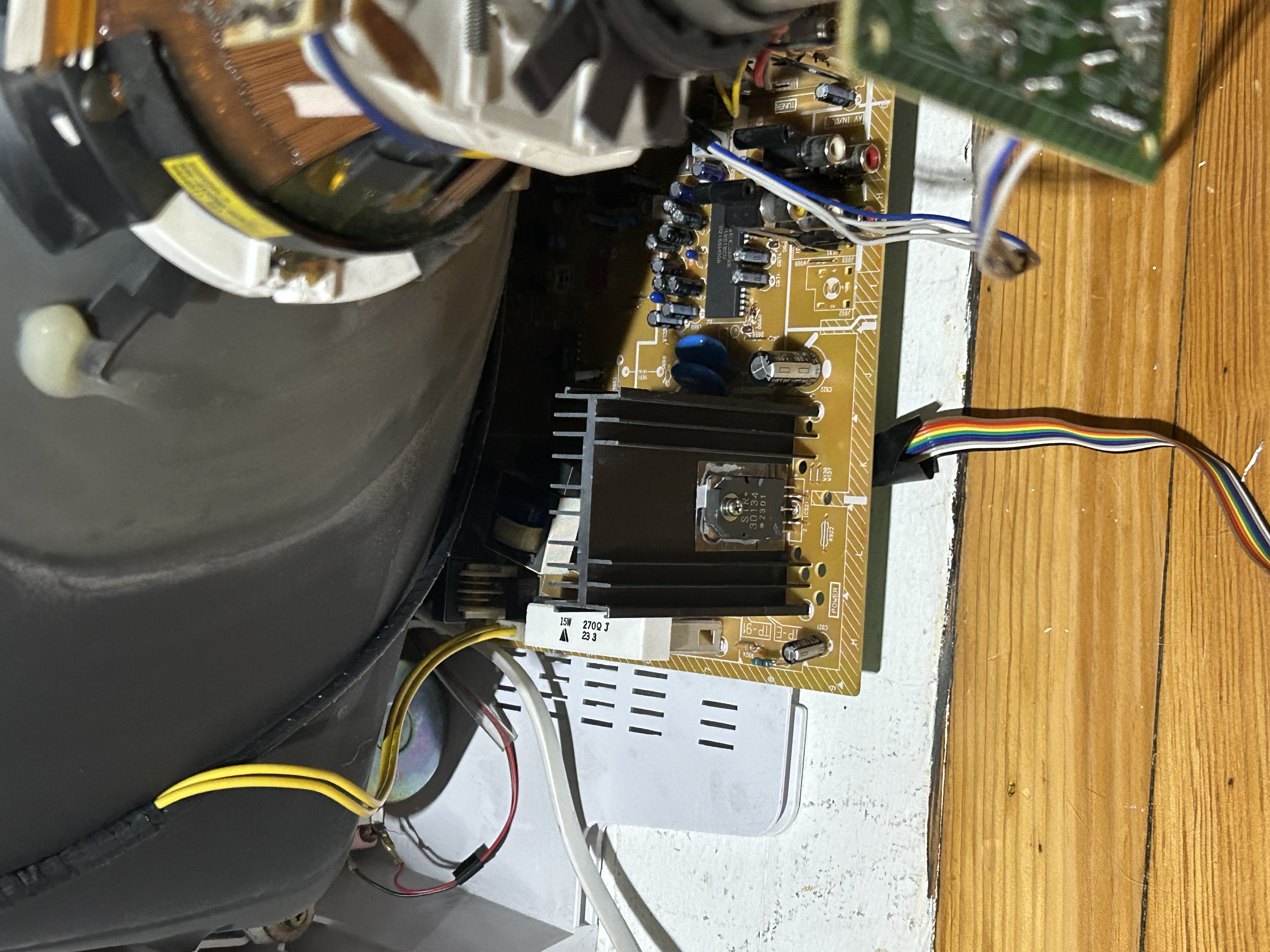
After opening it up and discharging the tube, I was welcomed by the cleanest CRT mainboard I had ever seen. Still, there was a thin layer of dust on the inner plastic that needed to be wiped off with a microfiber cloth. Minding the flyback transformer, I gently propped up the board to look at the underside.
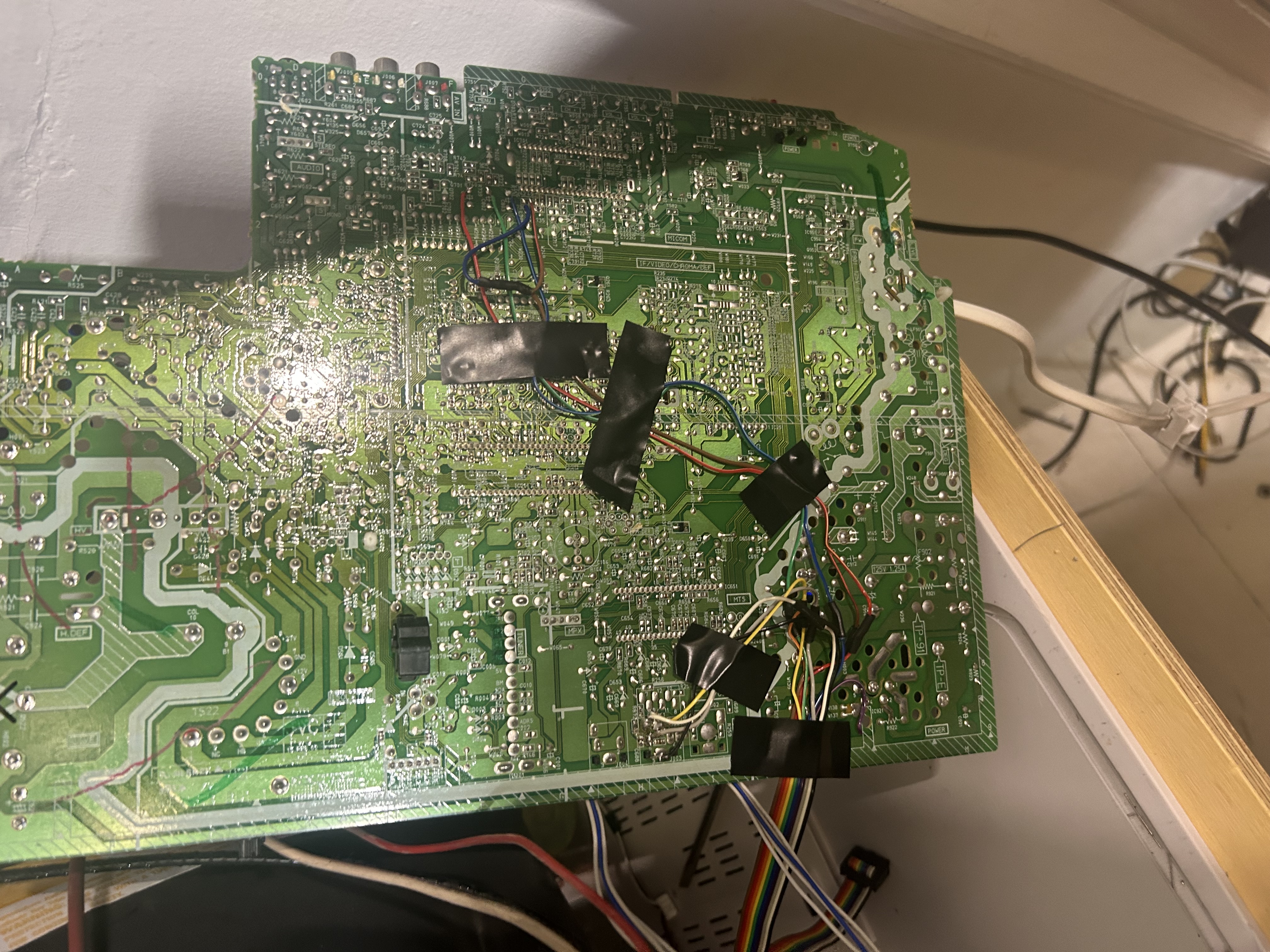
Step One - Sync and Ground
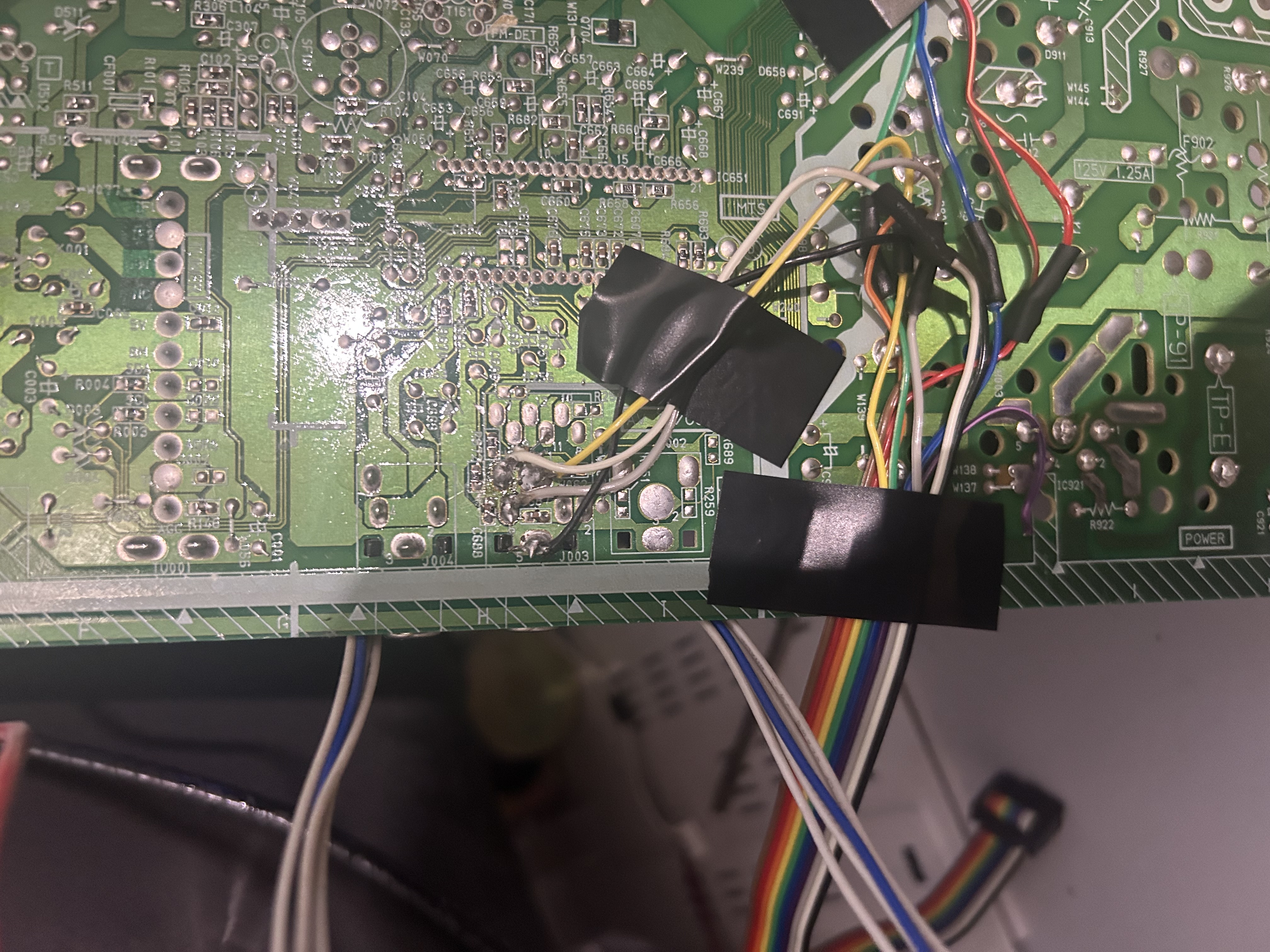
The easiest signals to get to the SCART connector are GND, Left/Right Audio, and composite sync. You can get these from any composite and audio input (assuming you use composite video as sync).
Step Two - RGB and Blanking
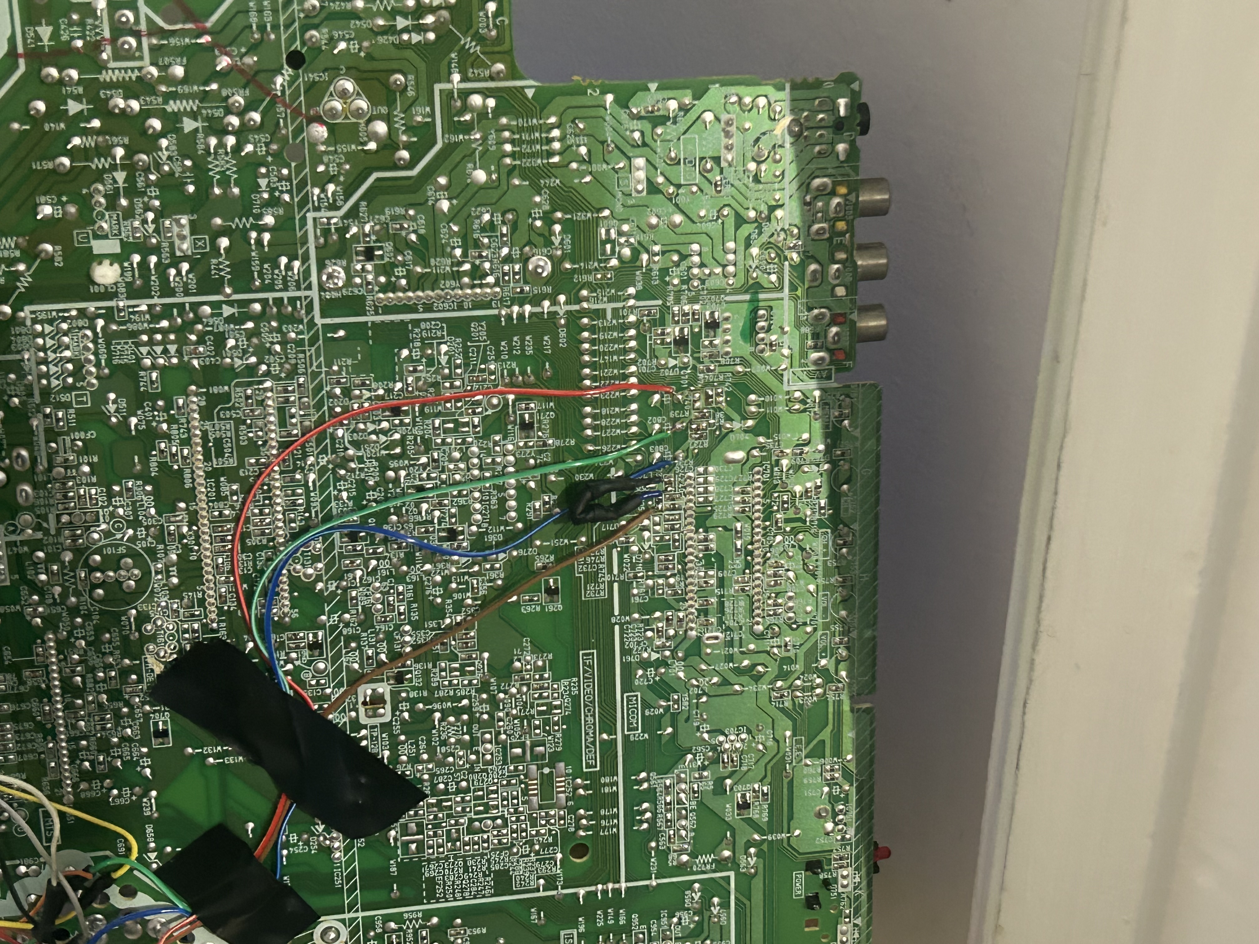
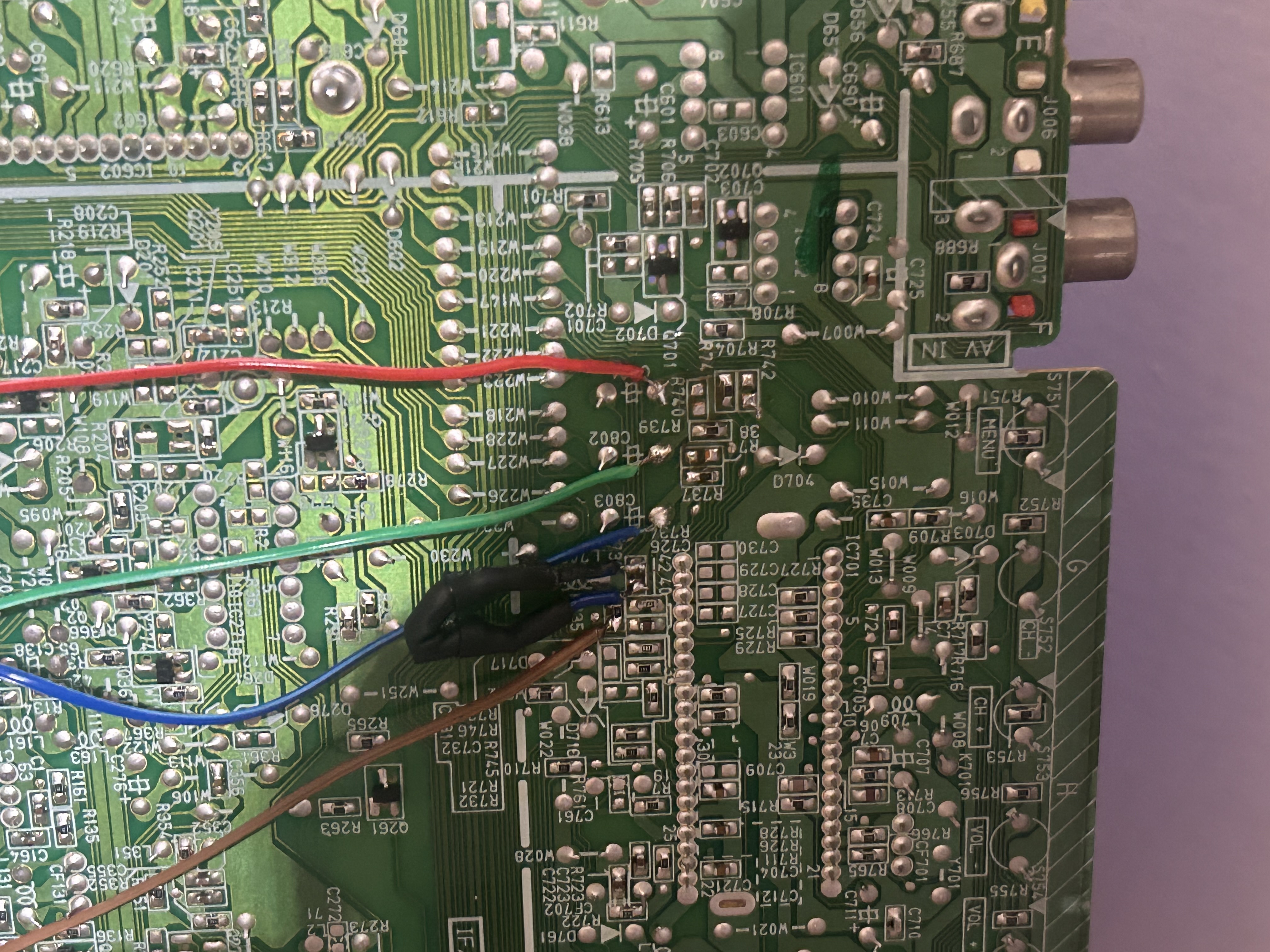
The RGB on this CRT is easy to find, as its position is identical to the AV-20020’s. After removing resistors R738, R740, and R742, you can get the un-terminated RGB signals from those pads. Blanking, however, was slightly moved from the 20020 to the 20320, so I had to look around for R735. The U-shaped wire is a resistor that replaced a 1K SMD resistor that I desoldered by accident. A dumb mistake, but not a costly one.
Step Three - Assembling My MUX Board
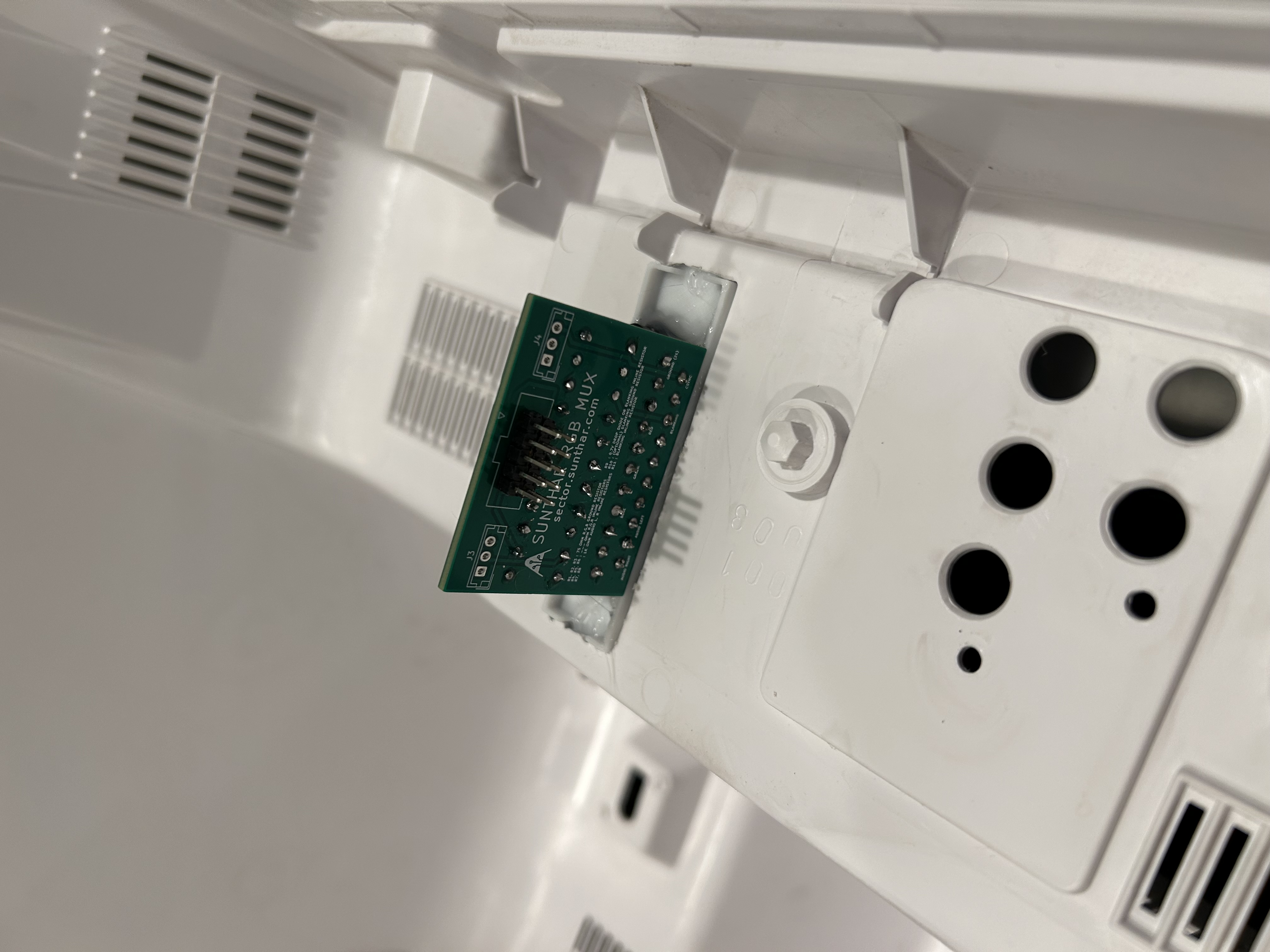
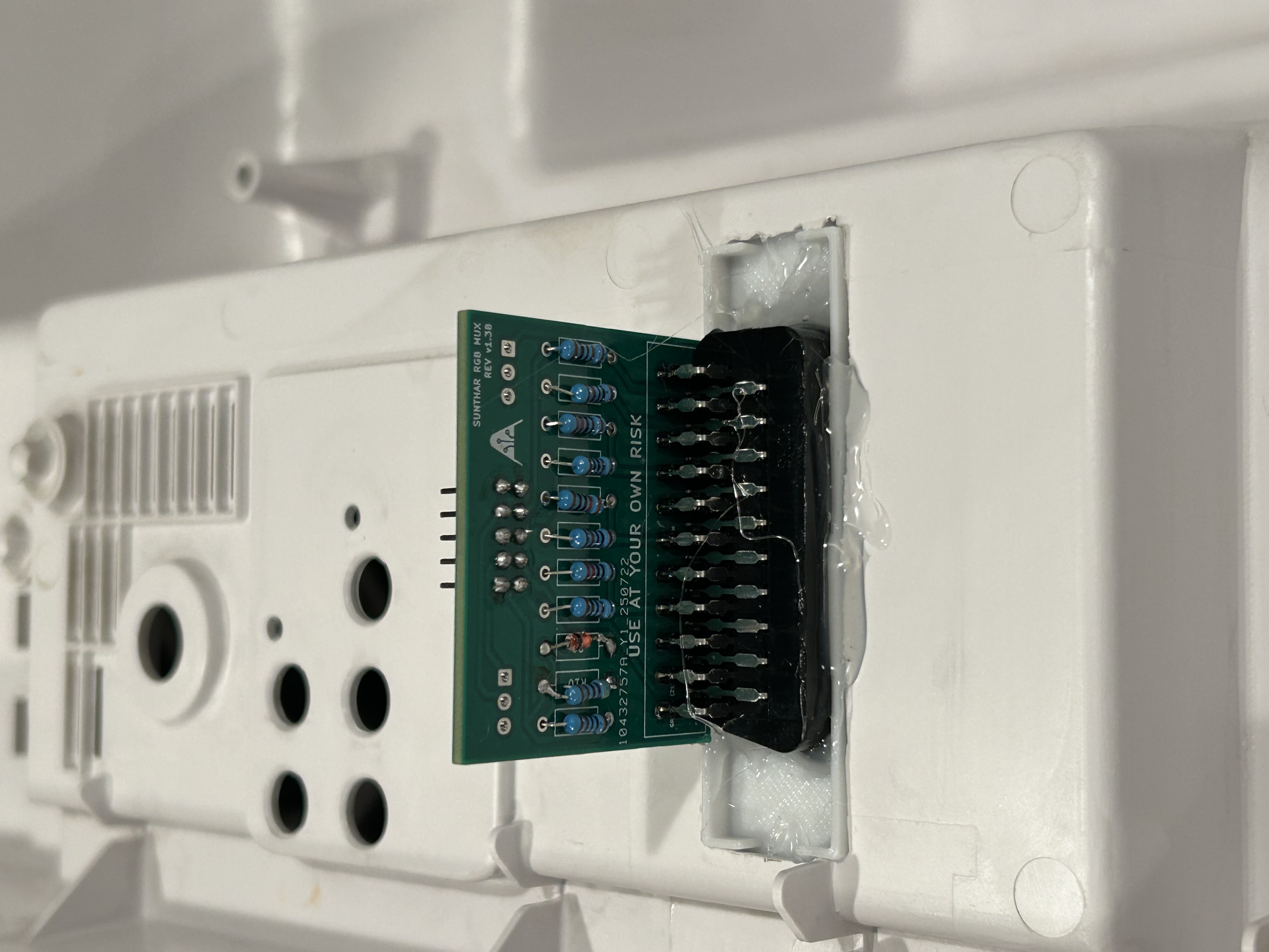
I soldered the MUX board using Sunthar’s recommended values for the AV-20020 and used standard pin headers for interface with the IDC Cable.
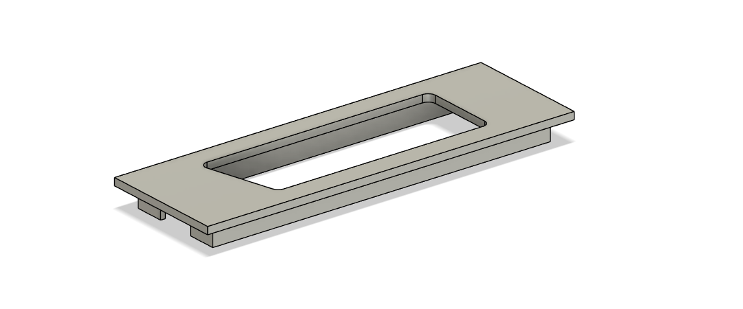
My SCART Connector Plate
So, at this stage in the mod, you’d typically need to use a Dremel, a drill, or a file to create a nice opening for the SCART connector. I’ve done this before, and it can be kinda stressful. However, seeing as I have a 3D printer, I decided to design a little plate for the connector. That way, you can just cut a crude 7x2 cm rectangular hole and glue the plate in for a nice opening. Sunthar actually already sells one of these on his store, but as far as I know the files are not free to download, so I uploaded my design here.
A Problem
So, here’s where I messed up a little. You’re supposed to plan out where the SCART connector/mux board will go, testing it to make sure that the board doesn’t hit anything or isn’t near any components that could cause significant interference. I didn’t do that; instead, I just found a nice-looking spot that I assumed would work.
It didn’t work at all.
I put the rear shell back on to test whether the CRT could be reassembled, but it couldn’t close up fully. Turns out that I had placed the board in a spot occupied by this big metal heatsink.
A Solution
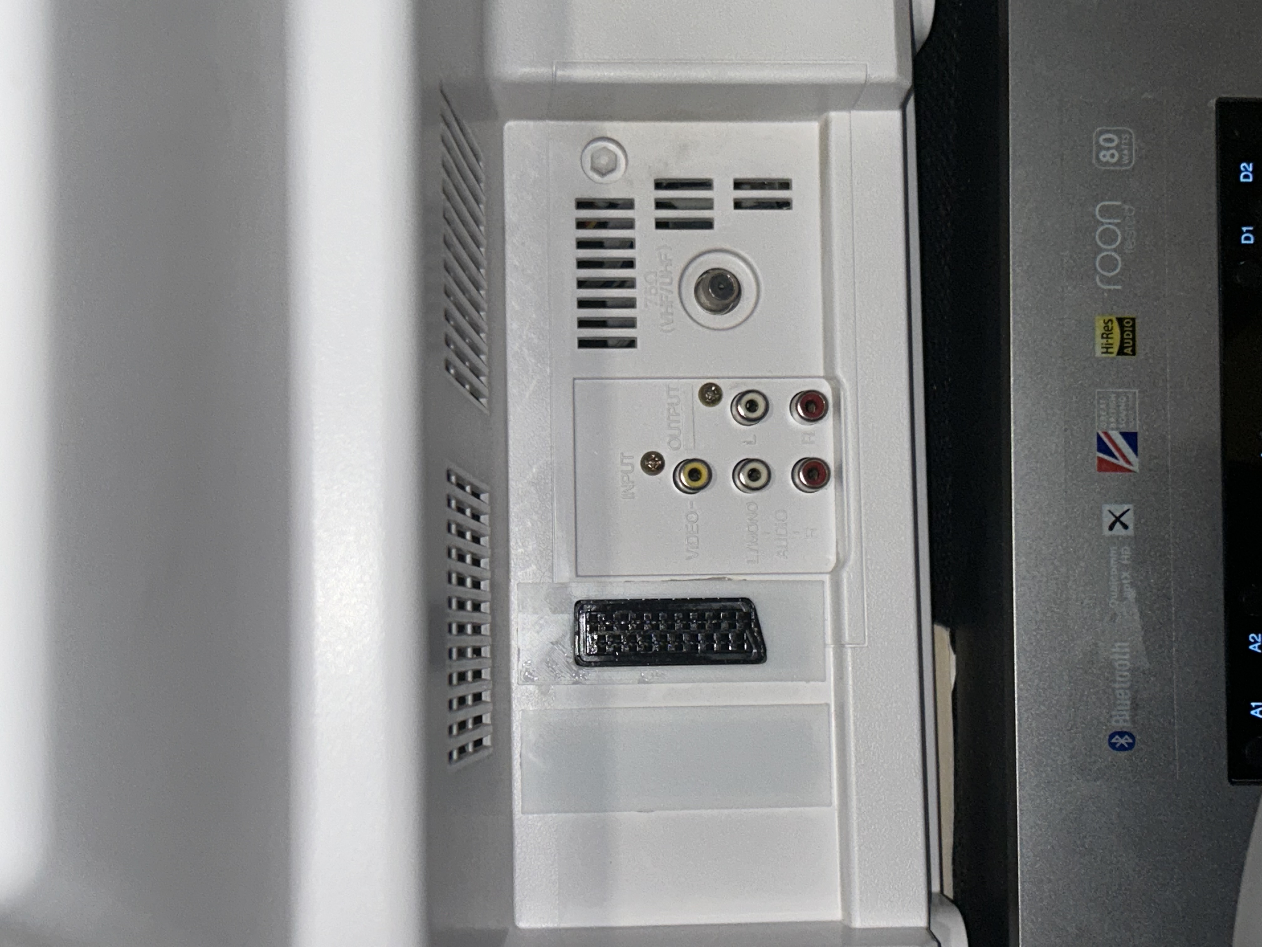
Luckily, I was able to move the connector over by a couple inches by cutting a new opening. I glued in a 3D printed blank panel to cover up the previous hole.
Here’s the final rear view of the CRT.
Troubleshooting
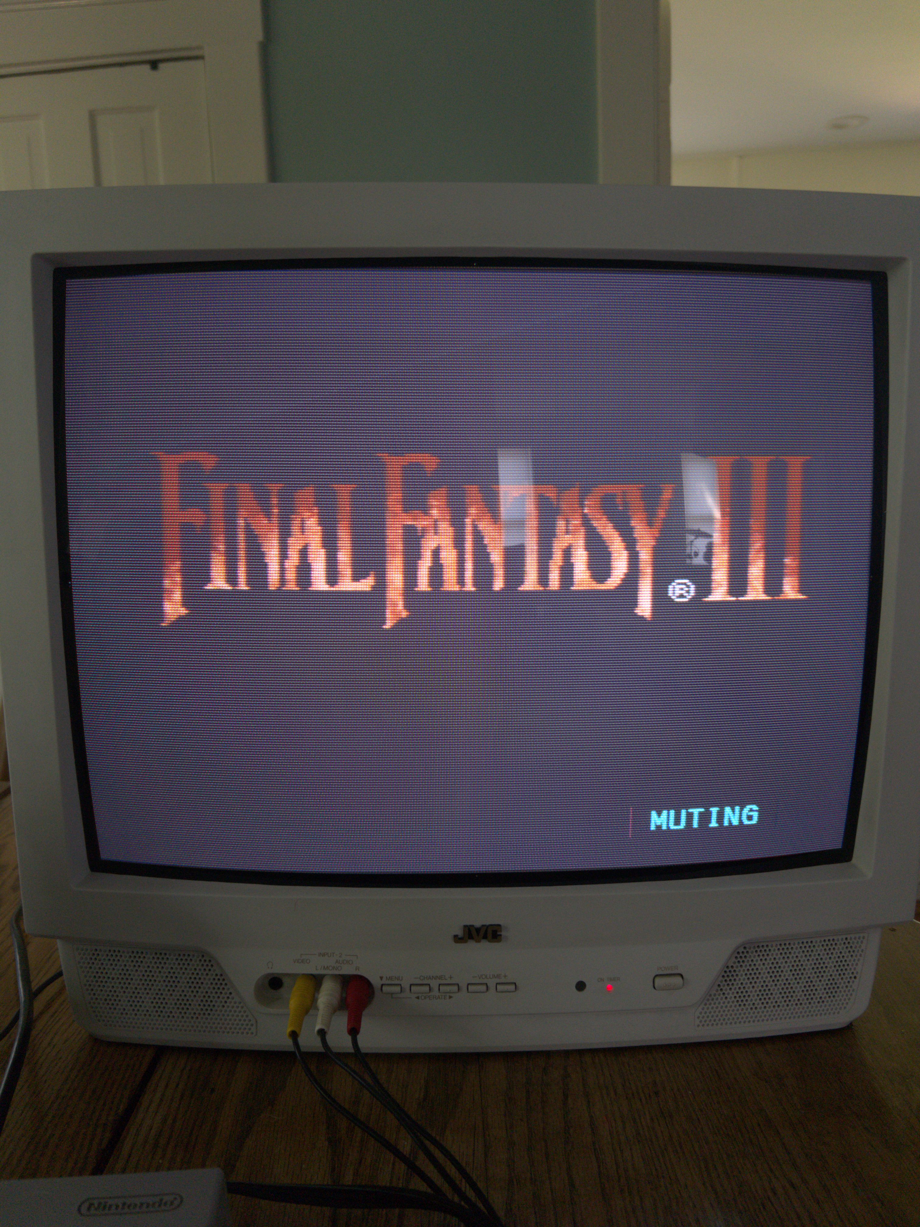
After reassembling the CRT, the mod seemed to be working, but there was an issue. While displaying an RGB input, the tube was far too bright, resulting in blacks that were almost light grey. After plugging my SNES in and booting up Final Fantasy VI, I could tell from the intro that something was off.
Ideal FFVI Intro

The JVC’s Washed Out FFVI Intro
Unfortunately, there was nothing that could be done via the service menu because the RGB signal overrides most of its video config. The only solution was to manually lower the very sensitive G2 voltage potentiometer on the back of the flyback transformer. It took a while to get it just right, but once I did the RGB signal looked fine; I set the brightness of the composite signal to something high in the service menu to compensate for the lower voltage.
With those final adjustments made, the mod was finished. I tried some more games on my SNES and took some before/after comparison shots.
Note: Getting good pictures of CRTs is hard. If you use a phone, you will need a camera app that lets you manually select ISO and shutter speed. I used an iPhone 14 Plus with the Lumina app, as it was the only one I could find that was free without any subscription. You’ll want to set the shutter speed to 1/60 (1/50 for PAL CRTs) and the exposure to something very low (I think I used 50).
Before/After
Chrono Trigger - Before
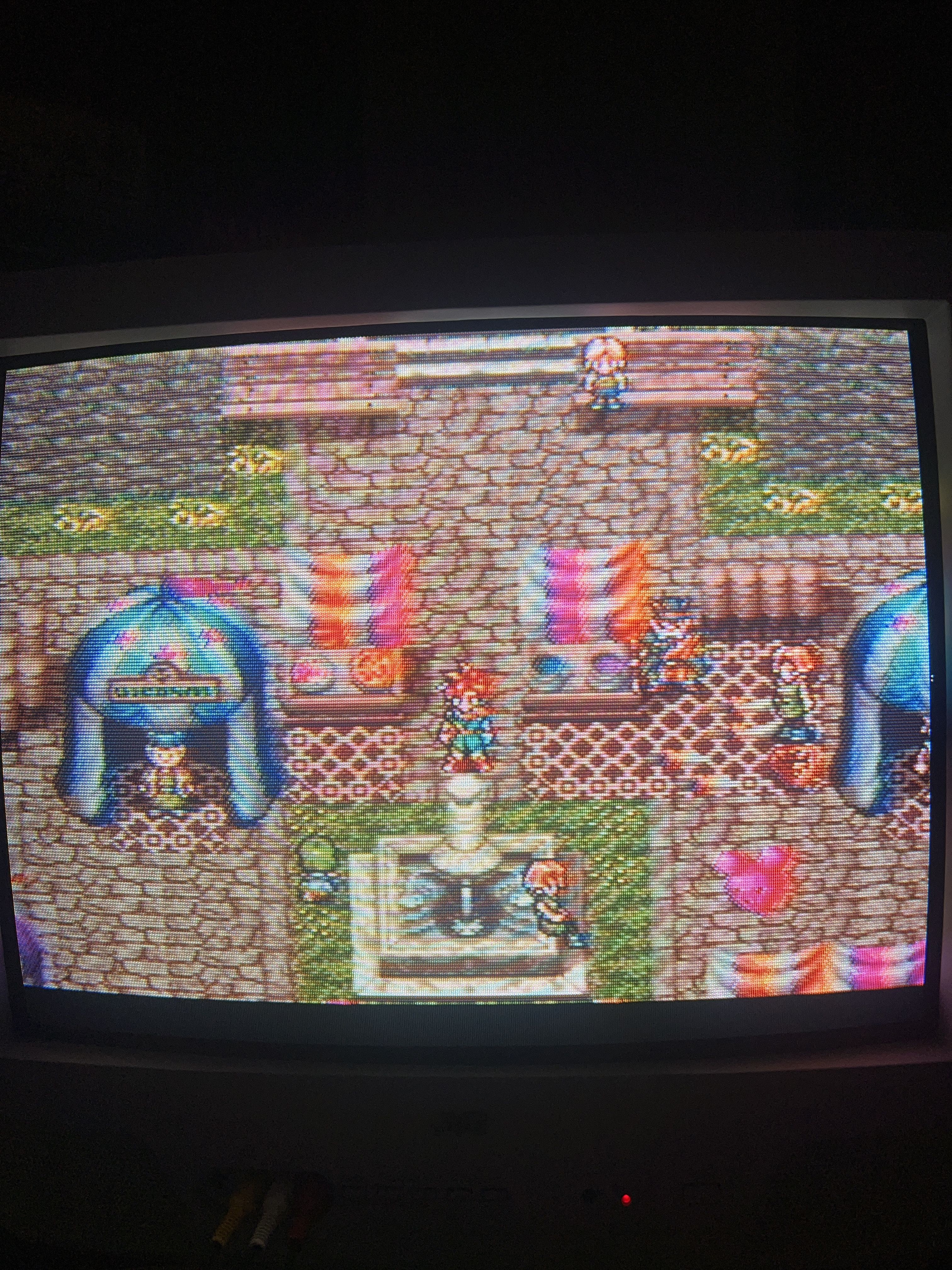
In this one you can see the “rainbow shimmer” effect that composite is notorious for.
Chrono Trigger - After

Rainbow shimmer be gone!
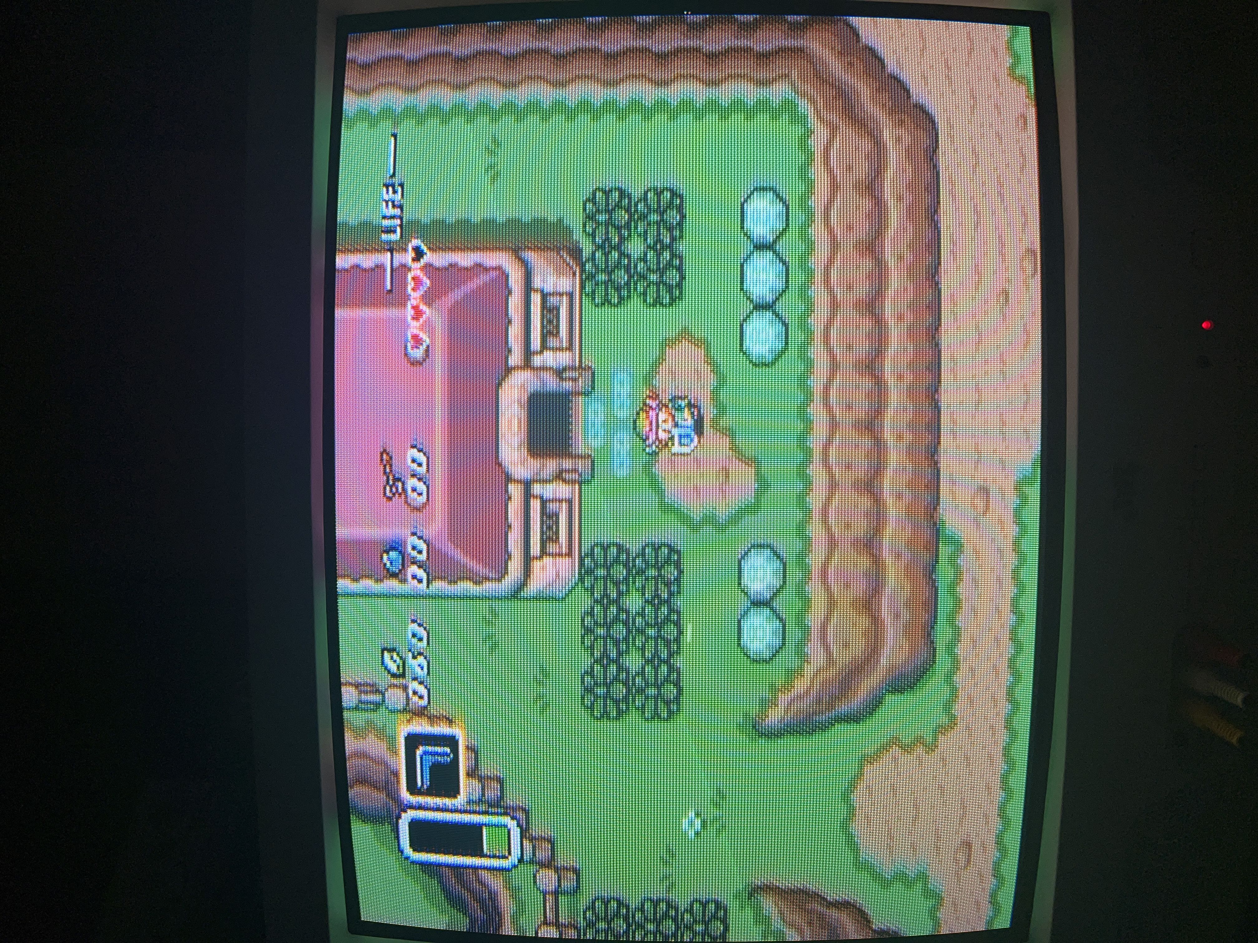
A Link to the Past - Before
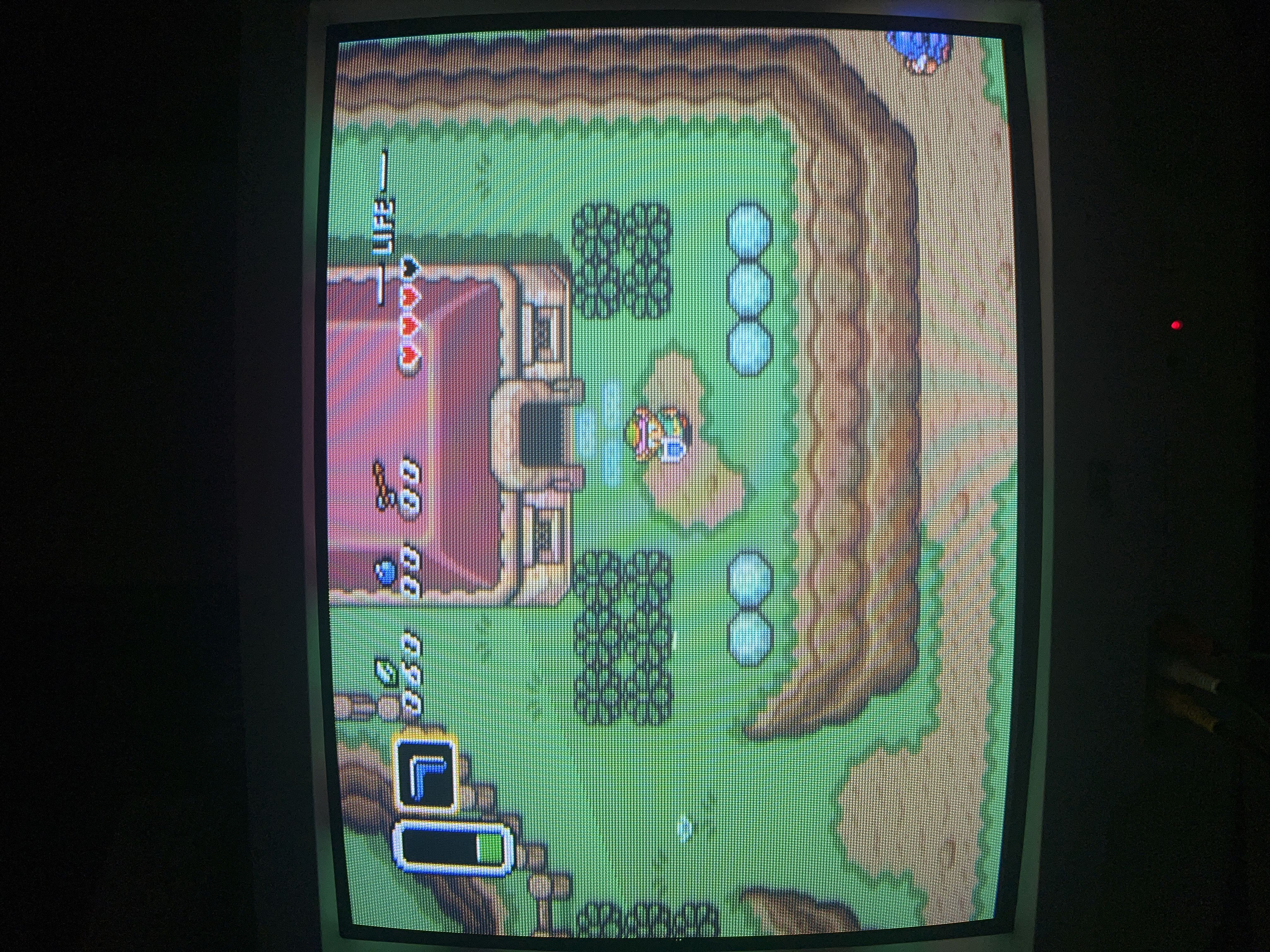
A Link to the Past - After
Contra III - Before
Contra III - After
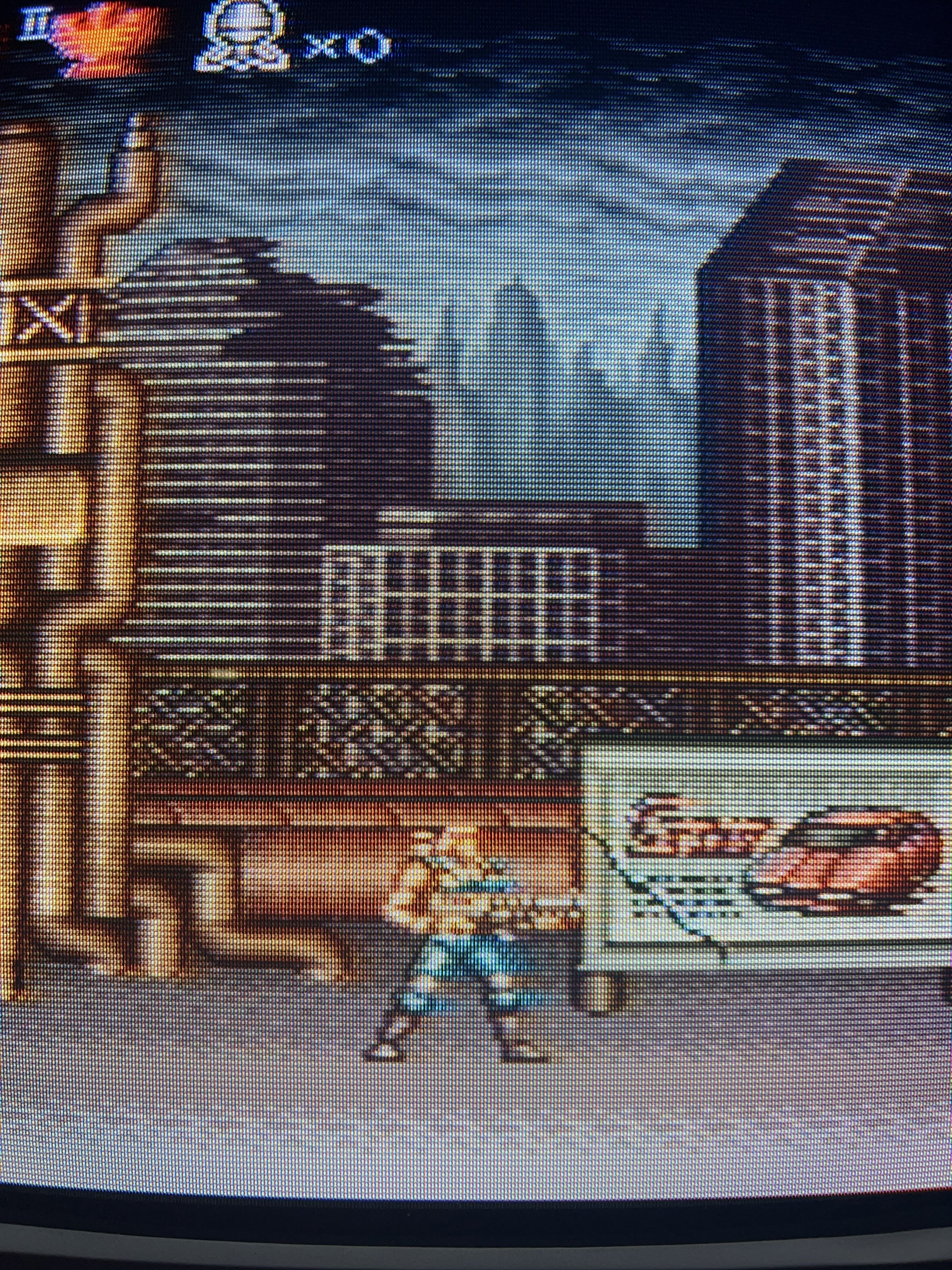
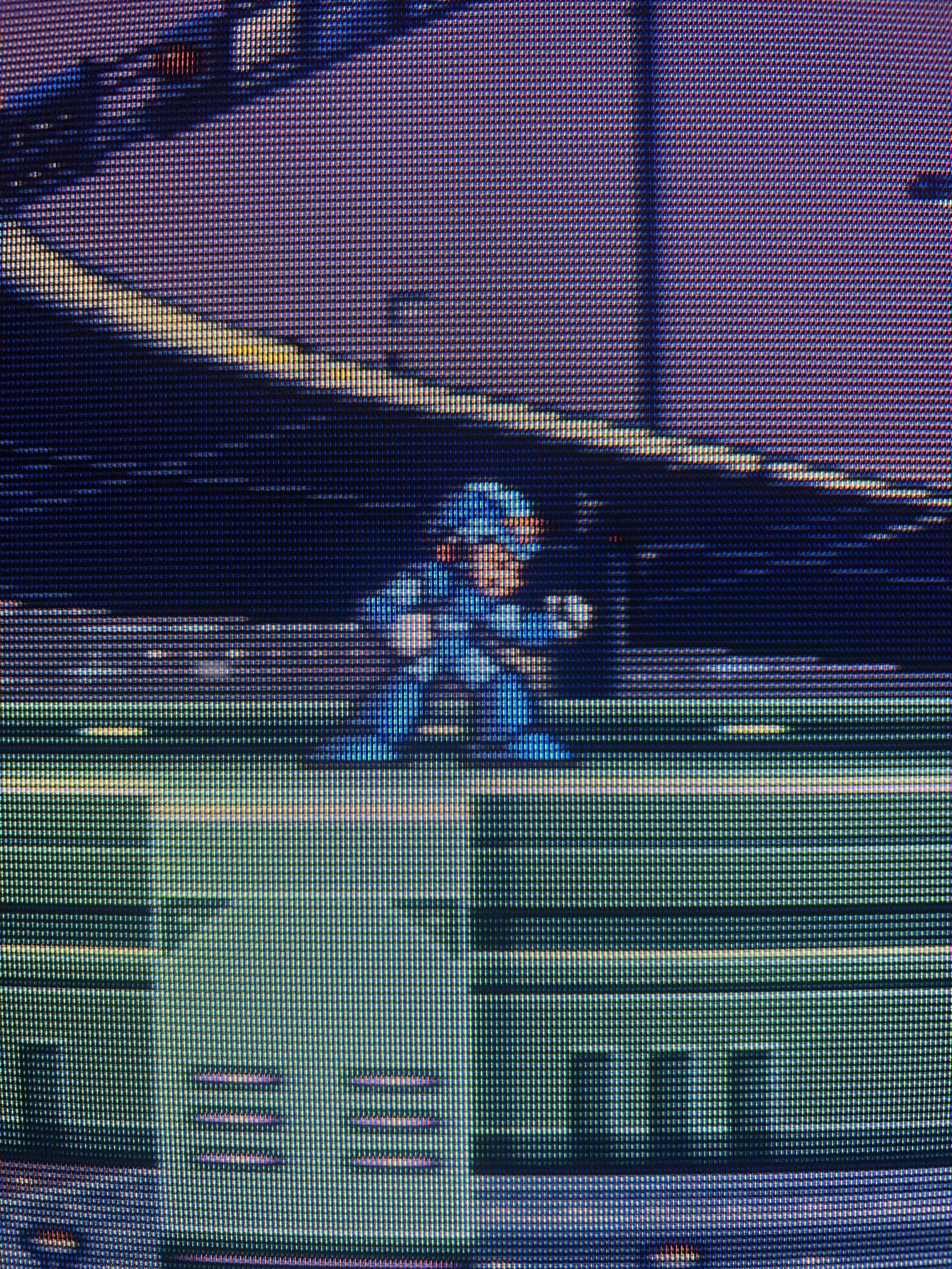
Mega Man X (Closeup) - Before
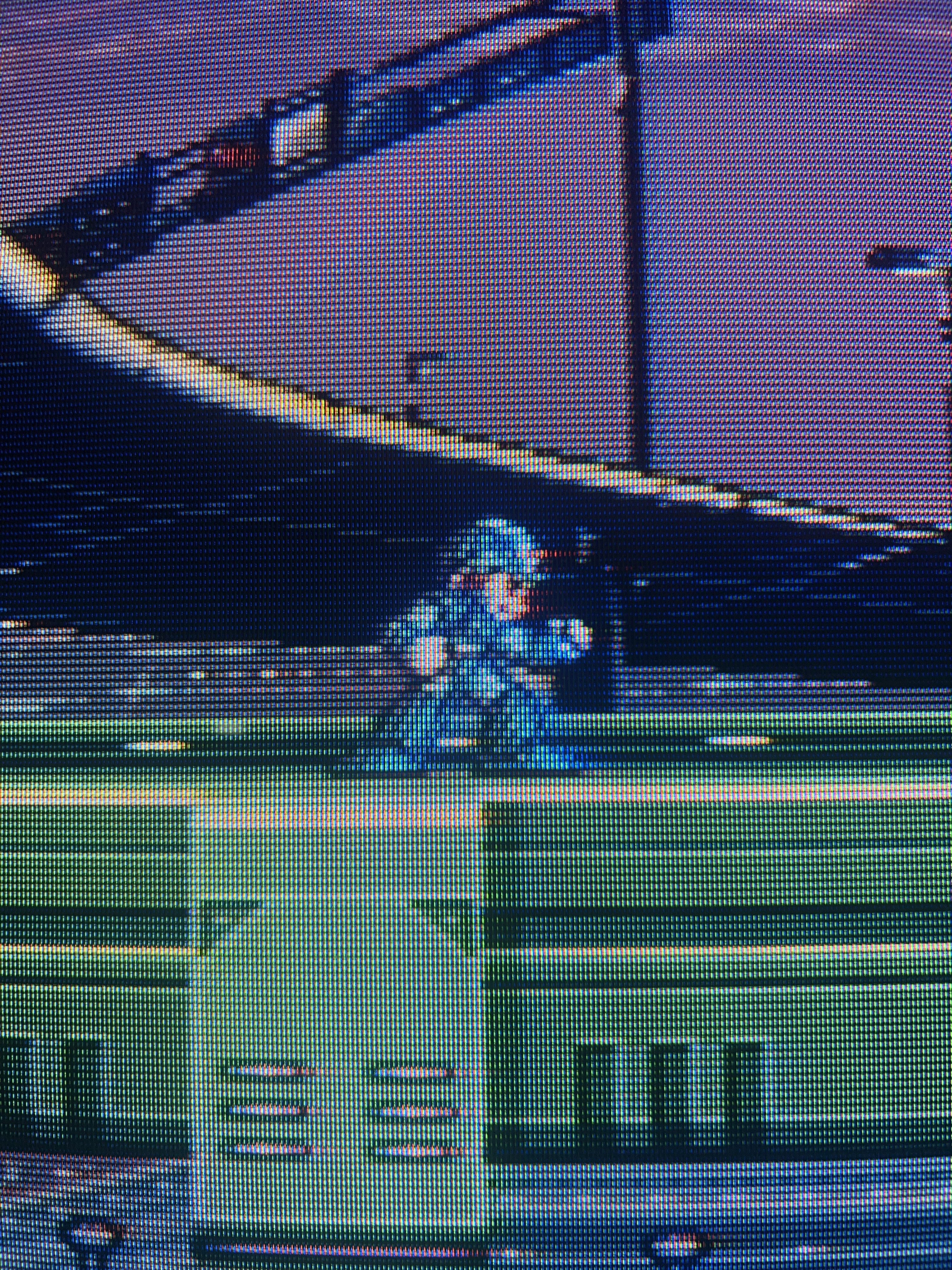
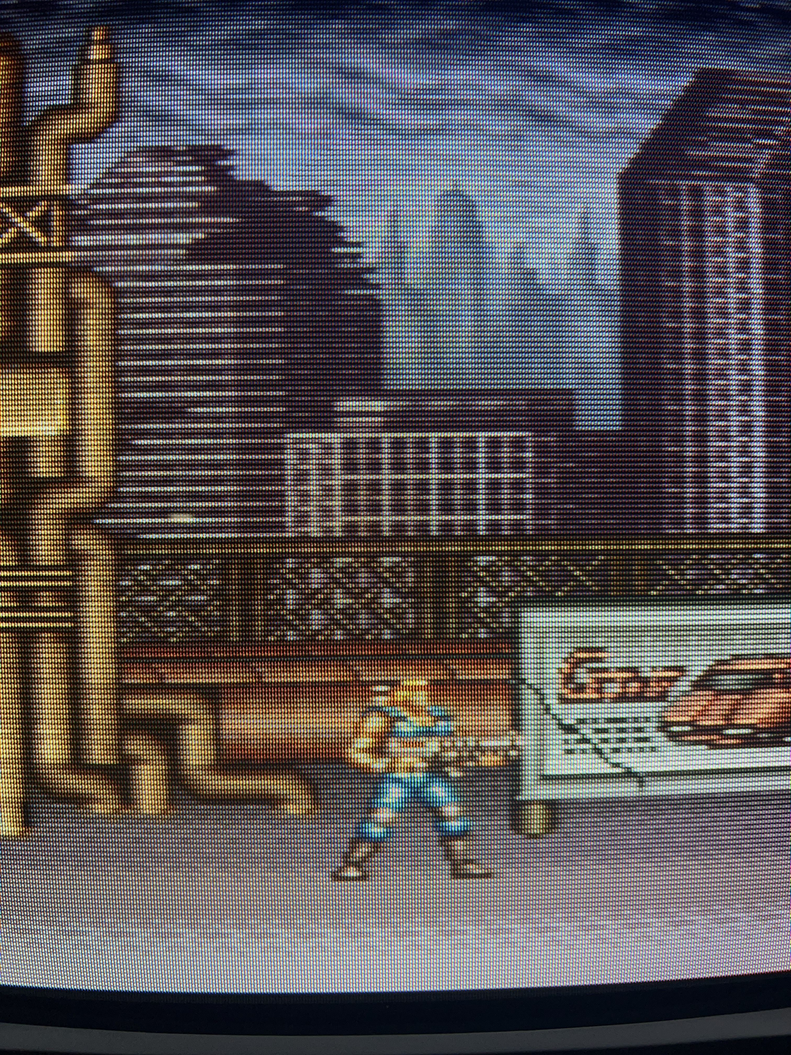
Mega Man X (Closeup) - After
Reflections
Overall, I’m extremely lucky to have a CRT as nice as this.

As you can see, the convergence is nearly perfect, even when using composite (if it wasn’t, those dots would be a blurry mess of red, green, and blue).
Honestly, besides the brief hiccup of placing the SCART connector in an obstructed location, this mod was pretty ideal; I really couldn’t have asked for a better result.