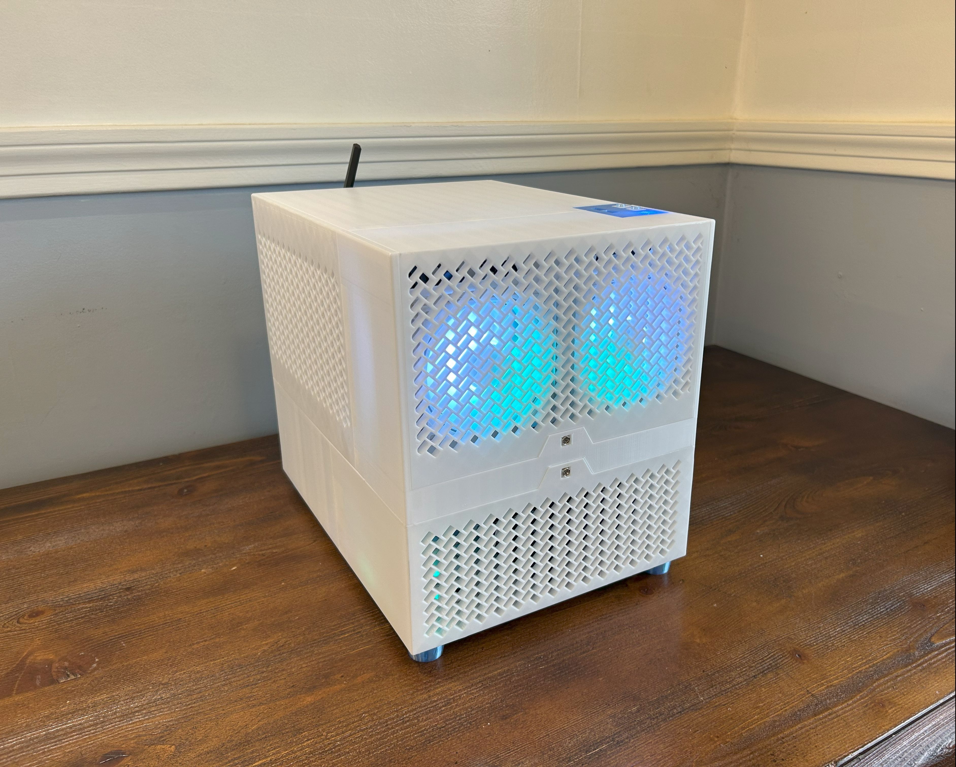
The Herringbone - A Custom Micro ATX PC Case
The original idea for this case came out of necessity. A friend that was short on cash asked me if I could build him a PC for around $120. I bought a cheap AM4 mATX motherboard, an RX 570, and an old Corsair ATX PSU. Already I was nearing the 120 dollar mark; I had yet to buy a case. Since I had bought a 3D printer just a few weeks before, I looked online for a cost-efficient case design that would fit my criteria, and found… nothing. Typically, 3D printed cases are designed to be as small as possible, meaning that they use ITX and SFX form factors that are much more expensive than the common mATX/ATX form factors. So, I figured I would make my first big Fusion project a practical one, and began working on a case that could support an mATX motherboard and an ATX power supply.
The Concept
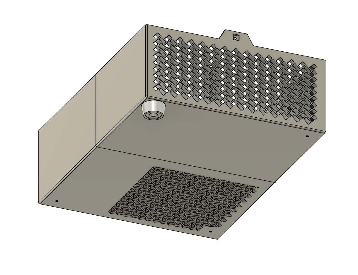
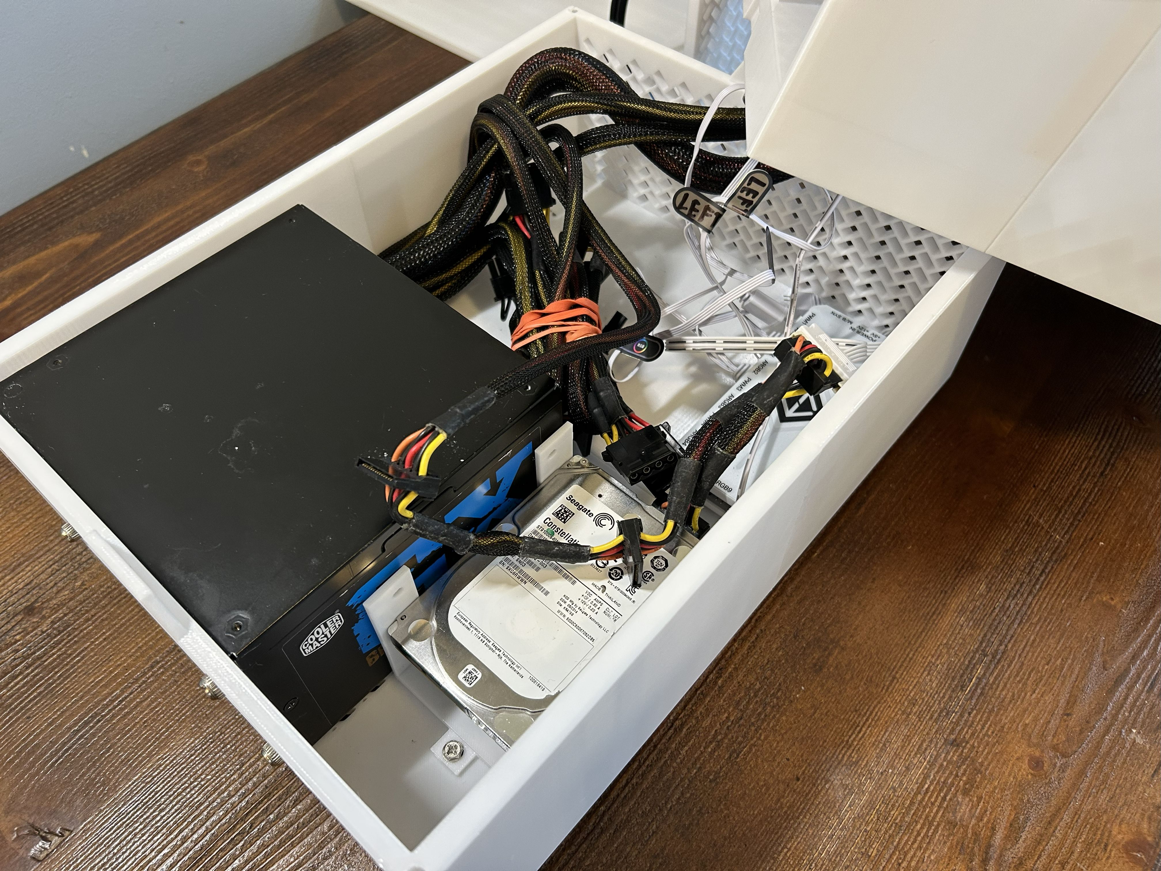
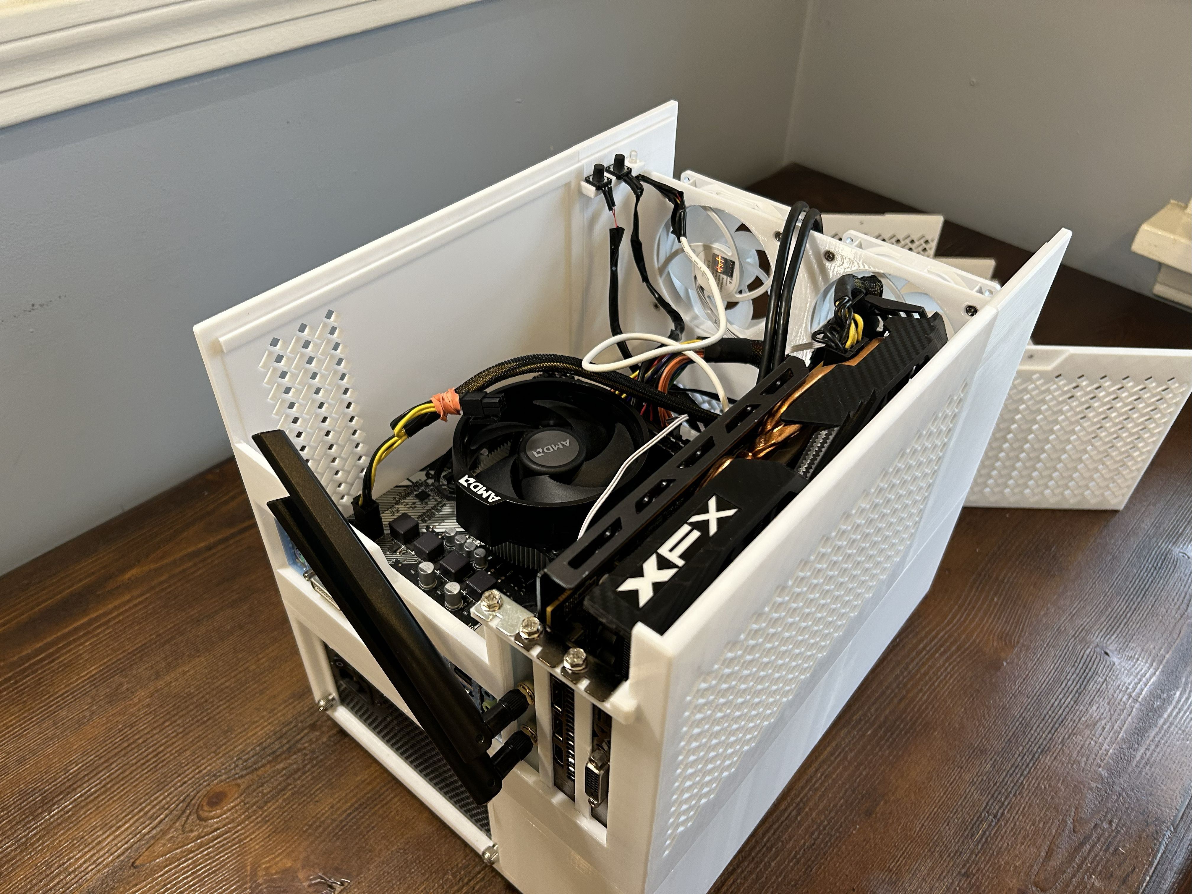
The initial concept for the design was to separate the case into two main compartments: a lower compartment that housed the PSU and HDDs, and an upper compartment that housed the motherboard, GPU, and fans. Rather than being vertically mounted, the motherboard would rest horizontally, further compacting the design.
I spent an unnecessarily long amount of time choosing the pattern for the fan grilles. The majority of cases use some kind of hexagonal pattern, but I wanted something more unique. I settled on a herringbone pattern, one commonly found in pavements, mosaics, and carpets, but rarely used in PC hardware. The case’s name would also be derived from this pattern (I’m really bad at naming things). 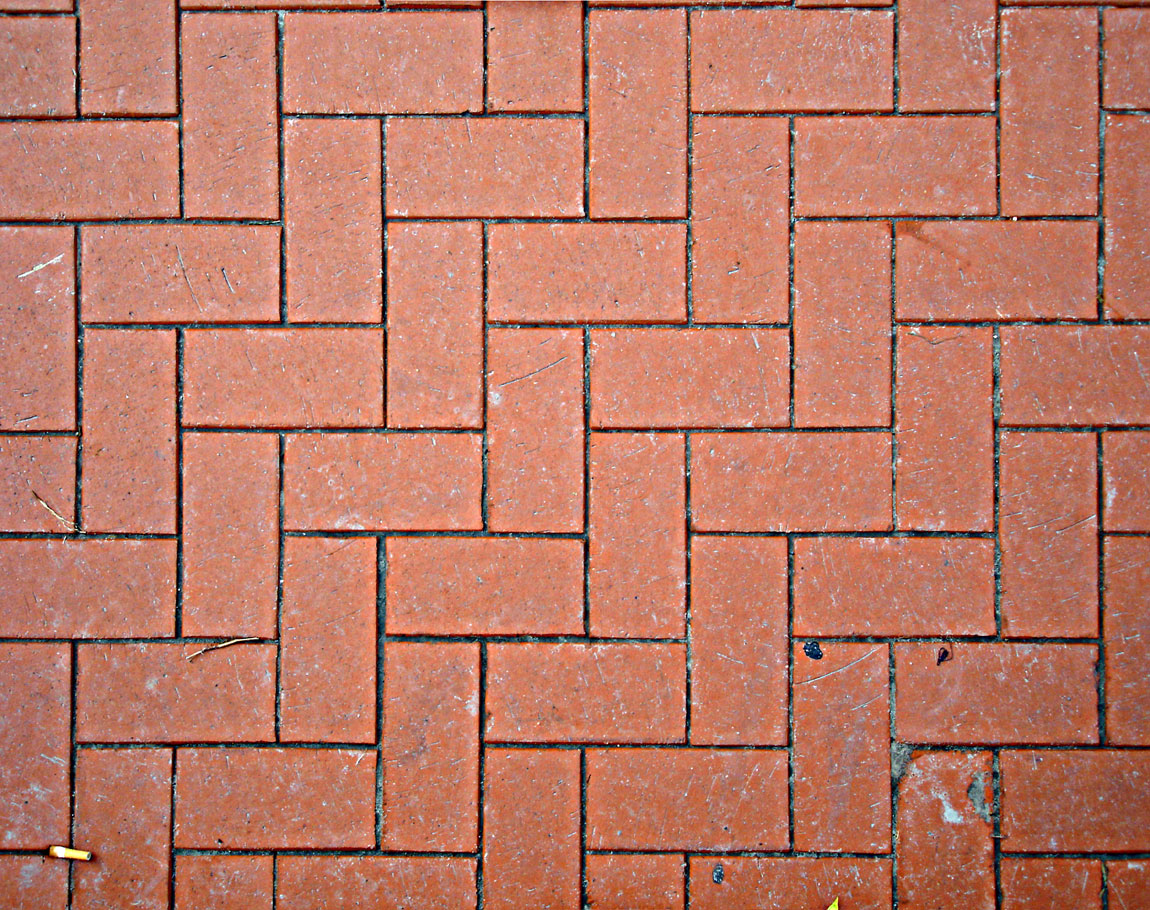
The actual hardware was pulled from an AliExpress kit that included M3 standoffs, PC chassis screws (#6-32 UNC), and M3 motherboard screws, which was all I really needed. I decided that, rather than printing plastic standoffs for the motherboard, I would use metal ones that would be sunk into holes of the case with a soldering iron. This would increase the overall durability of the case; small, printed threads are delicate and wear with use, and if the motherboard can’t be screwed into the case, the case becomes useless.
Why not just buy a cheap case?
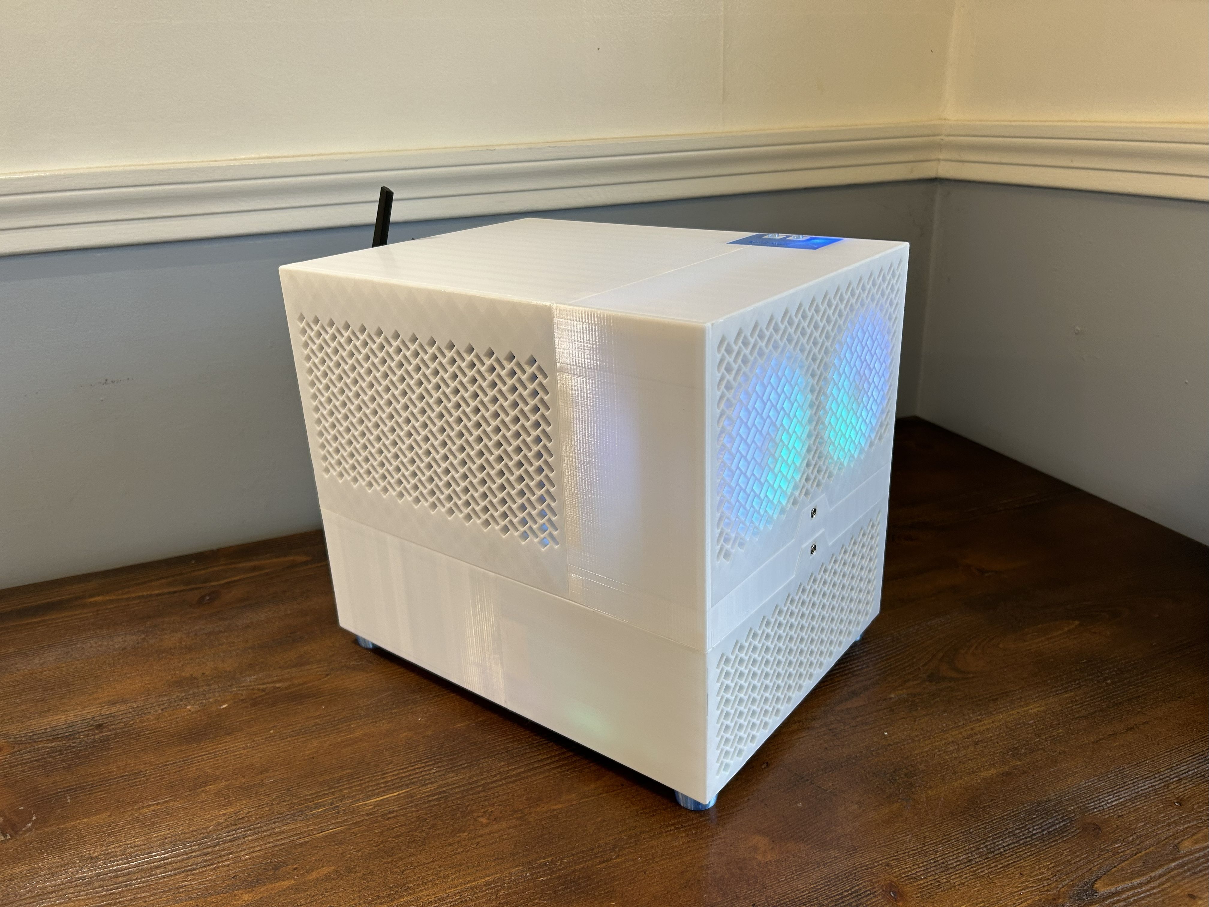
Generally, most people 3D print cases for small form factor (SFF) PCs, as 3D printing SFF cases is not only easier than printing large cases, but there’s also more of a reason to do it due to the high prices of many SFF cases. However, as I was going for the cheapest PC possible, I needed to use the very affordable mATX standard, which is much cheaper than the ITX size that most SFF cases use. While the cheapest mATX cases available generally cost around $55 new, a full Herringbone cost me less than 15 dollars (around 1.4 KG of filament plus buttons and screws).
Design Overview
The case is comprised of 3 main segments: the cover, the upper assembly, and the lower assembly.
The Cover
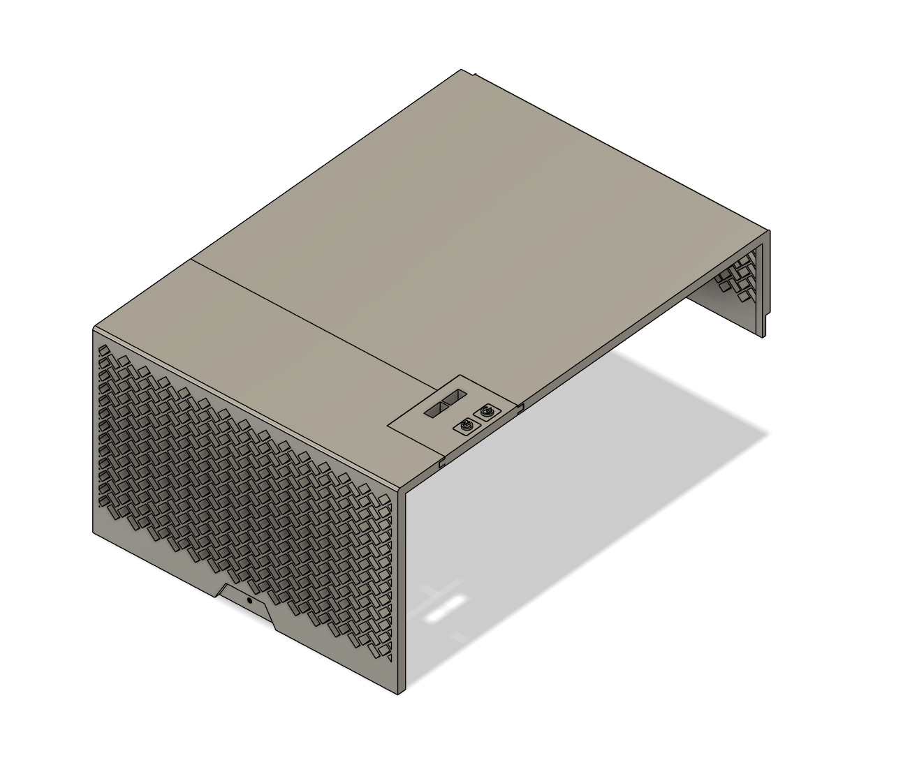
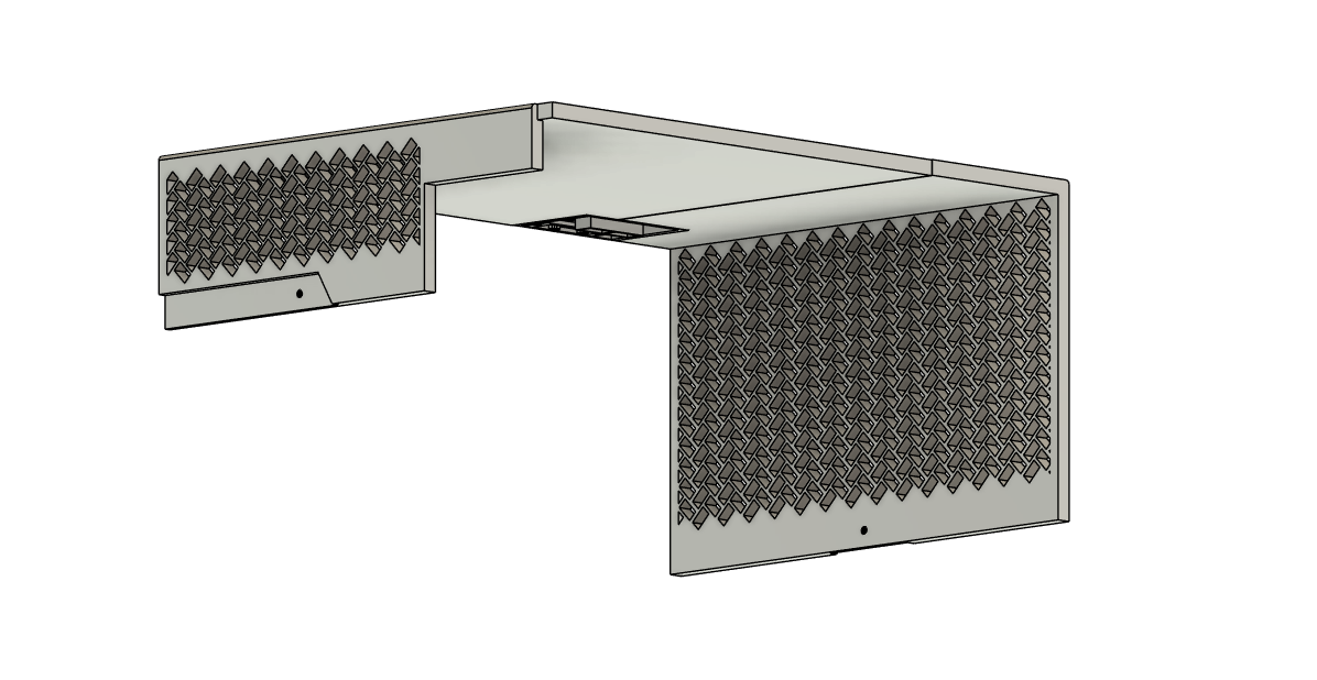
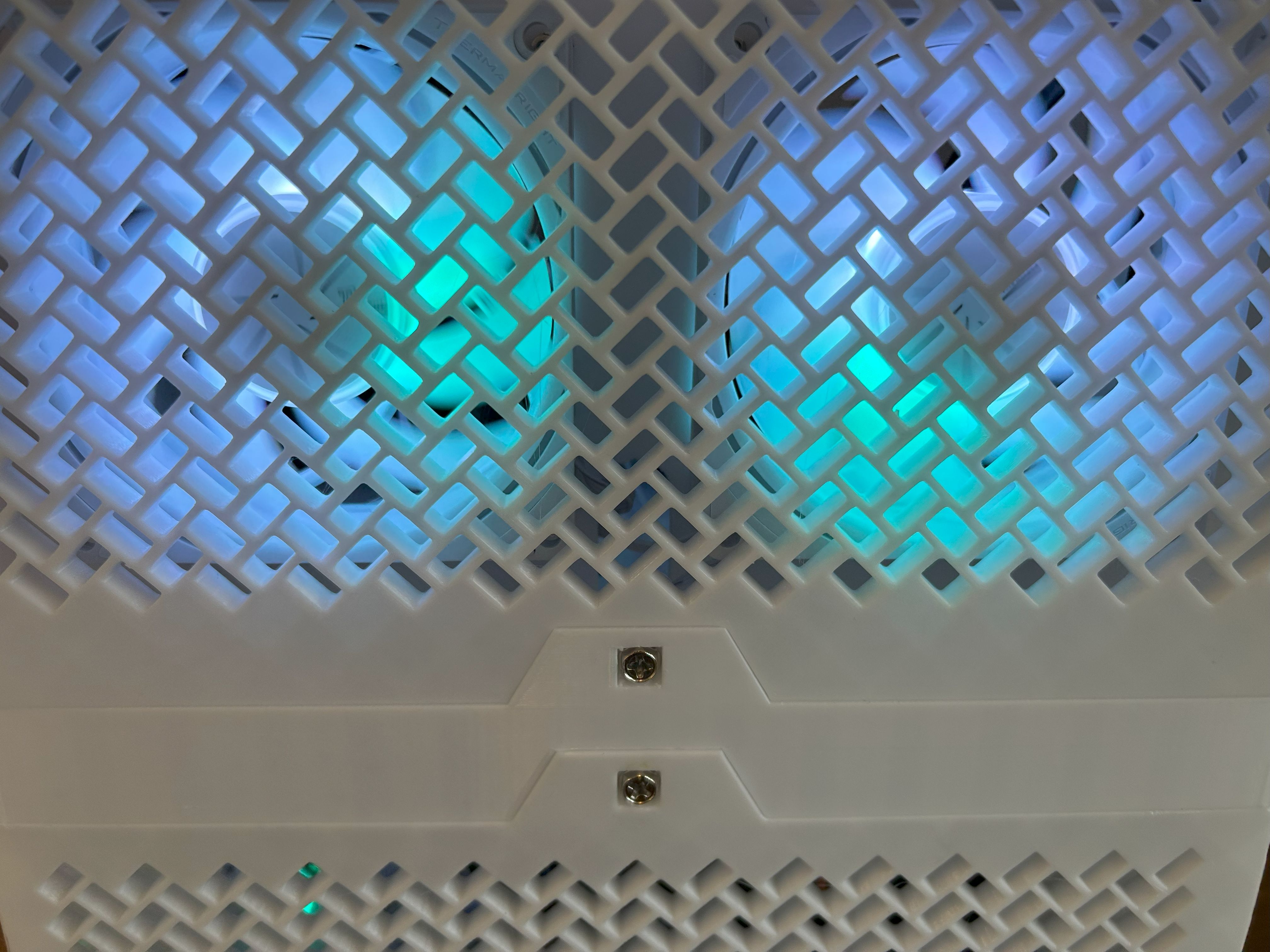
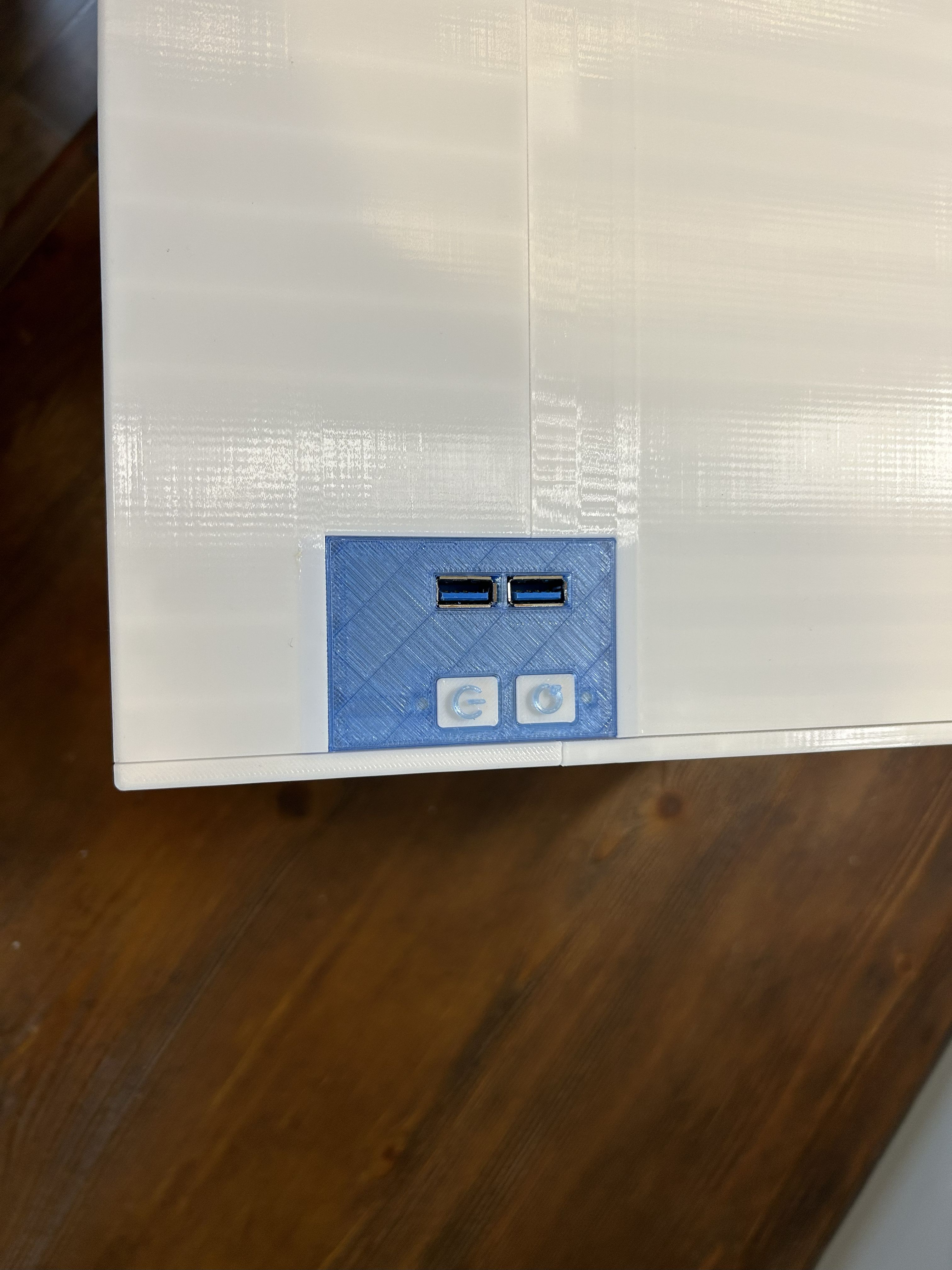
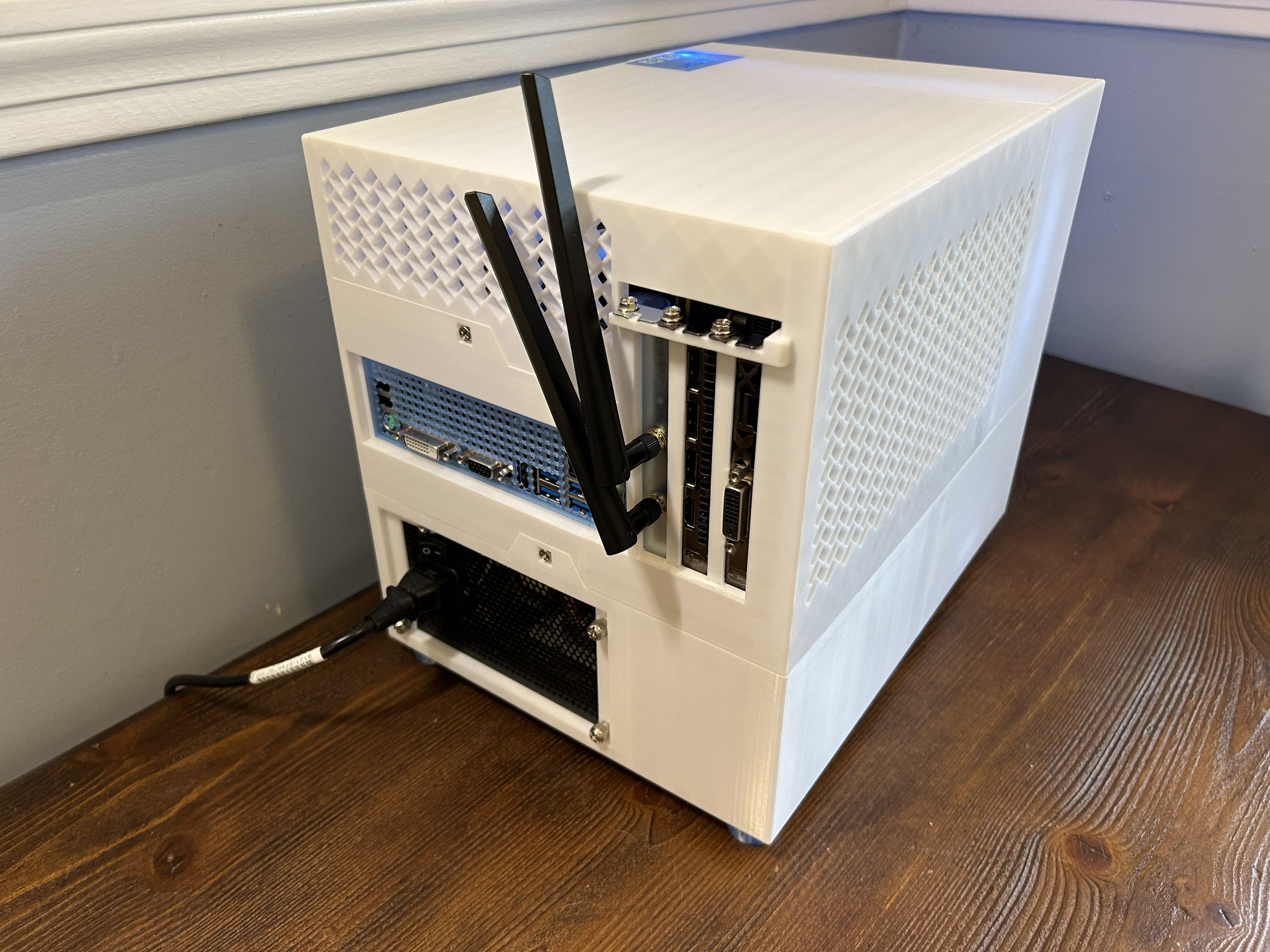
The cover simply encloses the case and completes the exterior. It’s made up of 3 sub-segments: the front segment, the rear segment, and the I/O panel. The front and rear segments have herringbone-patterned fan grilles that provide airflow to the case, allowing cold air to enter via the front two intake fans and exit out the rear as hot air. The I/O panel is a bit more complex and features cutouts for 2 buttons (power and reset) and two USB 3.0 ports. On the underside of the I/O panel, there are threads for the attachment of a button bracket that holds the buttons in place. The entire cover has two trapezoidal notches that allow the cover to be secured into the upper assembly with chassis screws.
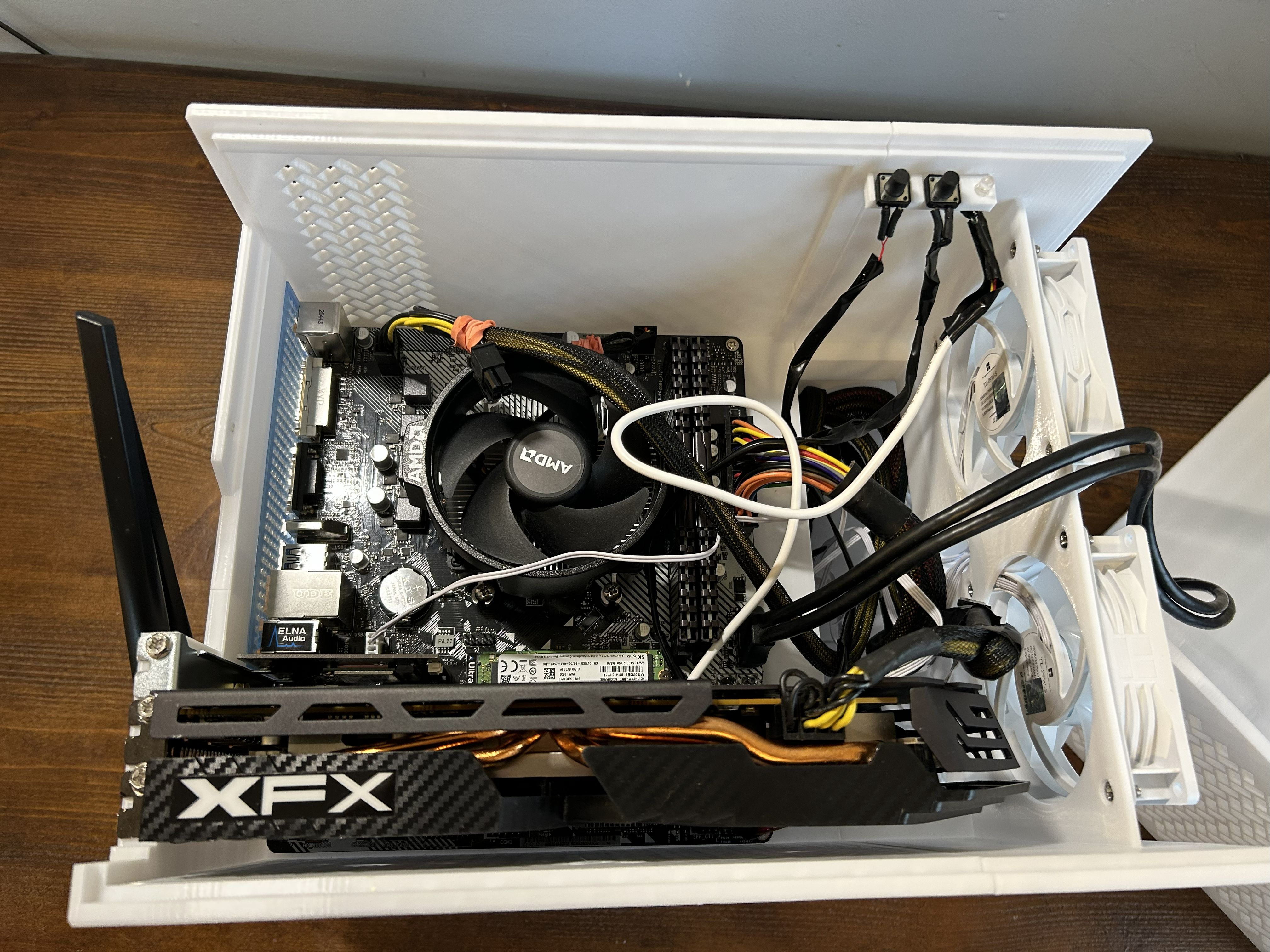
The Upper Assembly
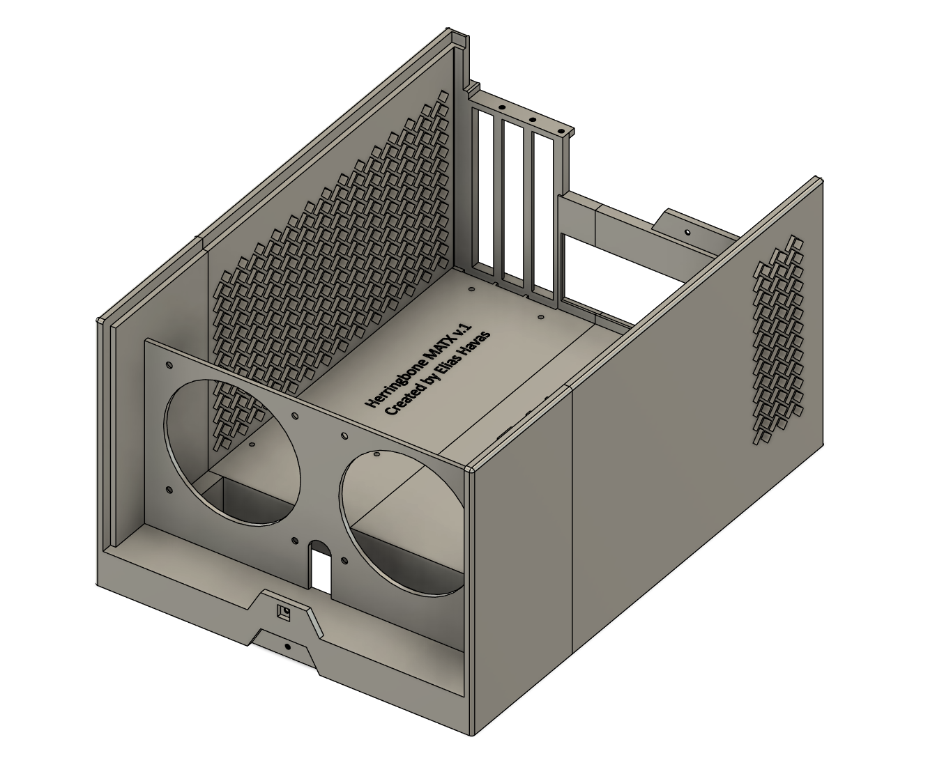

The upper is the most complex piece of the case. It houses the Motherboard, CPU, and GPU. Immediately behind the front cover, the upper allows for the installation of two 92mm intake fans. Directly behind the two fans is a large open trench, allowing for cables to be routed from the PSU and hard drives in the lower assembly to the components housed in the upper assembly. The majority of my time working on this project was spent on tweaking the positions of the motherboard standoffs and GPU/PCIE components, as the precise specifications meant that their alignment needed to be almost perfect. Airflow is handled by a left-side fan grille for GPU exhaust and a smaller right-side grille for general ventilation. Like the cover, the upper has two trapezoidal notches that secure it to the lower assembly with chassis screws.
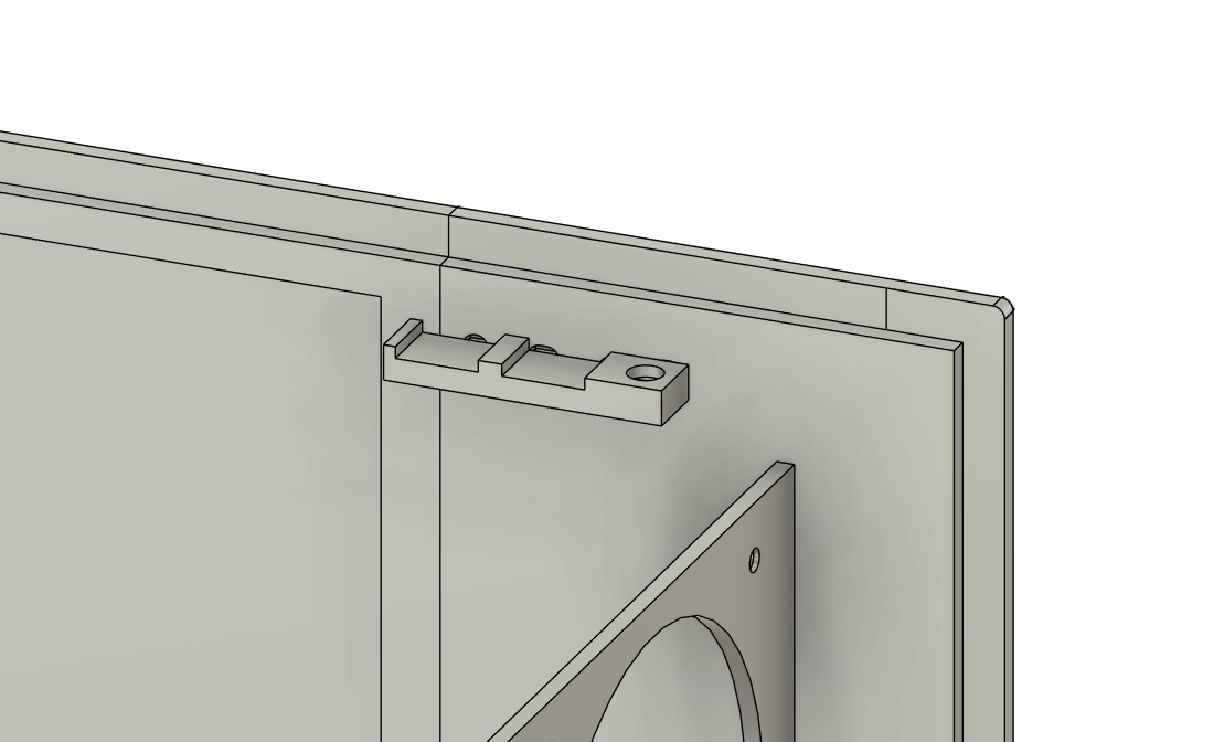
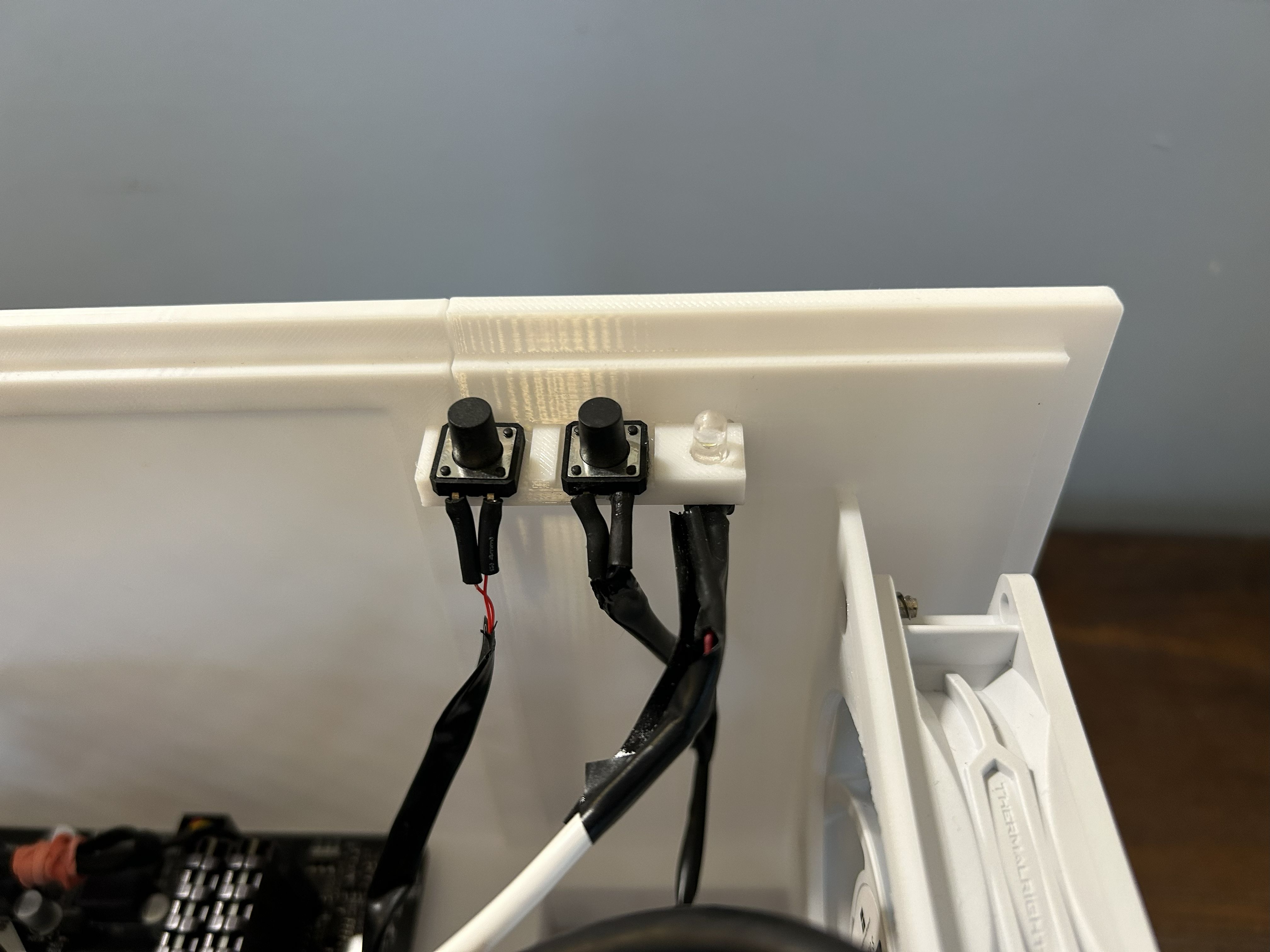
Another defining feature of the Herringbone is the I/O brace. It’s a continuation of the front I/O panel mentioned in the cover section, and it provides a backbone for the buttons and LED to be glued onto. The buttons I used were 12 x 12 x 12 mm pushbuttons, and any 5mm LED will work fine.
The Lower Assembly
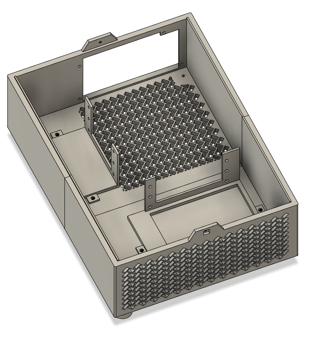
The lower houses the power supply and, optionally, up to 3 3.5” hard drives and 3 2.5” hard drives via modular caddies.
The Feet
To top it all off, I made some cool feet for the case that are screwed into threads on the bottom with chassis screws.
Download and Pictures
If you want to print this case yourself, here’s the Printables link.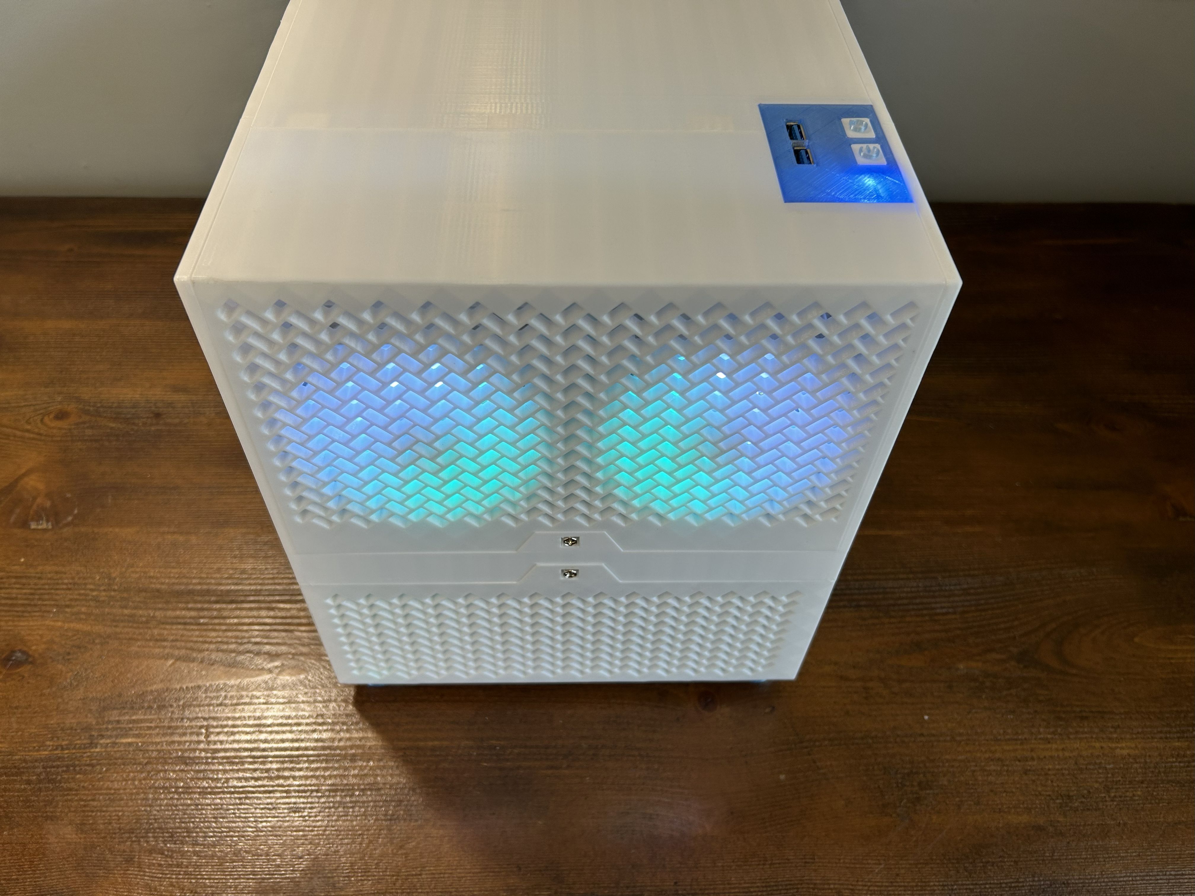
Reflections
I finished designing this case in February of 2025, after over a month of work. By the end, I was much more comfortable with Fusion’s workflow, having learned the importance of tolerances (push-pull tool, my beloved), multi-segment printing, and designing to minimize supports. I printed way more prototypes than I probably should have: about 7 spools of PETG were spent on trial and error. Not long after the project’s completion, I discovered that you can cut out sections of a CAD file directly in Orca Slicer; if I’d known that earlier, I could’ve saved a ton of time and filament. I printed my final Herringbone for my friend in white SUNLU PETG with transparent sky blue accents (I/O shield, front panel, and feet).
Overall, for my first large, assemblied CAD project, I think it turned out quite well.